
Oil burning system

a technology of oil burning system and oil, which is applied in the direction of incinerator equipment, combustion types, lighting and heating apparatus, etc., can solve the problems of relatively inefficient waste oil burning system and high level of pollution, and achieve the effects of reducing emissions of carbon monoxide, reducing fuel consumption, and increasing efficiency

Inactive Publication Date: 2010-03-11
ENERGY EFFICIENCY SOLUTIONS
View PDF48 Cites 15 Cited by
  • Summary
  • Abstract
  • Description
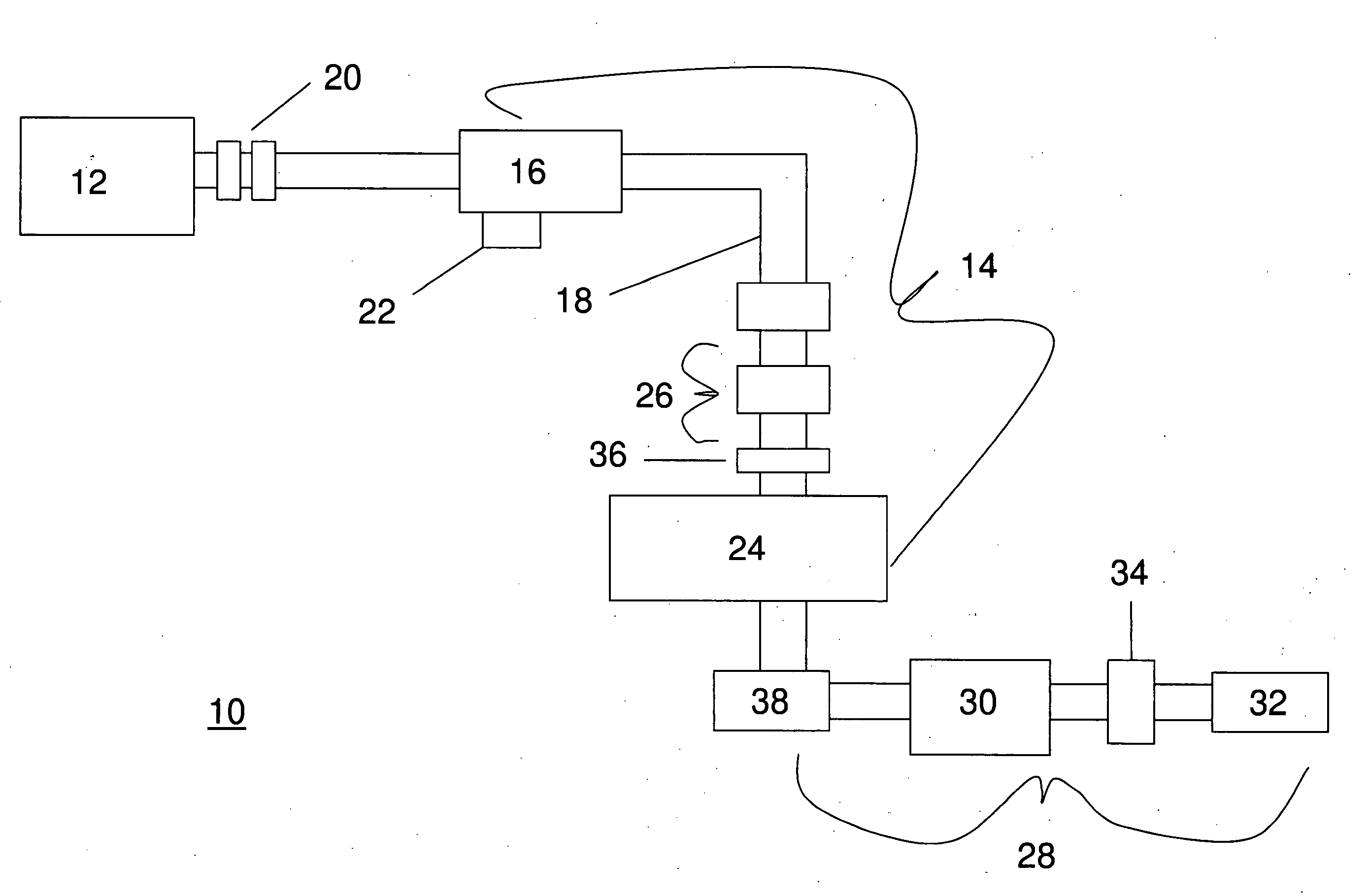
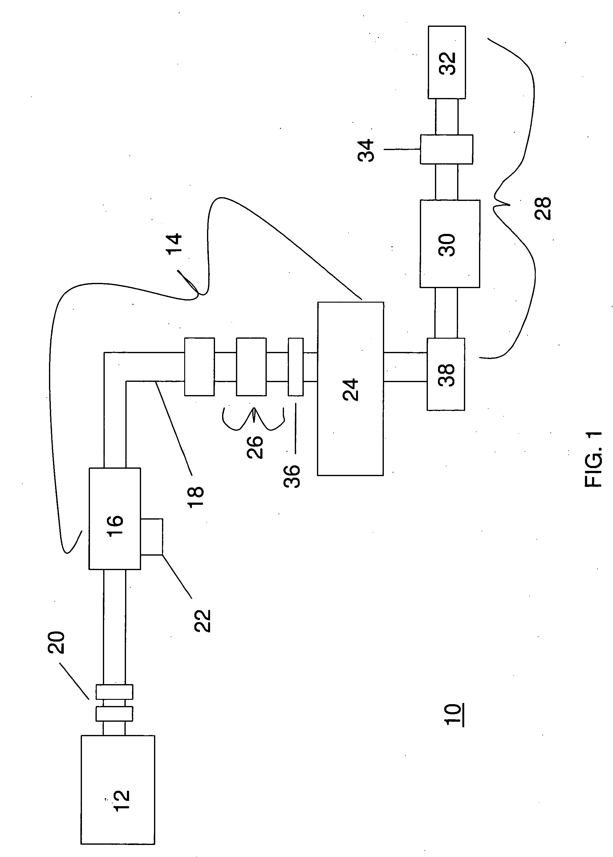
  • Claims
  • Application Information

AI Technical Summary

Benefits of technology

[0006]The primary object of the instant invention is to produce an oil burning system that increases efficiency by reducing the amount of fuel usage through the presence of high pressure within the system, along heating the fuel under high pressure.
[0007]Another object of the instant invention is to produce an oil burning system with reduced emission of carbon monoxide, hydrogen sulfates and hydrocarbons, and without creating sludge as a byproduct of operation.
[0008]Another object of the instant invention is to produce an oil burning system that comprises the ability to automatically adjust the flame size to maintain a constant stack temperature to maximize efficiency.
[0009]According to one embodiment, the present invention operates in the following manner: the fuel is pumped out of the storage tank by an ultra-high pressure pump which increases the pressure of the liquid fuel to approximately one thousand nine hundred pounds per square inch and passed through a two-stage high-pressure filter, into a pre-heat tank; after the fuel temperature is raised, the fuel is dispensed through a nozzle and is ignited. By monitoring the exhaust stack temperature of the system, and varying the pressure accordingly, optimal heating efficiency can be reached. Initially, when the system is cold, increasing the pressure substantially, allows the flame to burn at a higher level than that of existing systems, while not increasing the volume of liquid fuel utilized. As the water temperature of the boiler rises, the pressure is gradually reduced. Optimal efficiency is reached by monitoring the stack temperature and adjusting the pressure to keep the stack temperature at about four hundred and ten degrees Fahrenheit—the pressure is reduced when the system detects the stack temperature above four hundred ten degrees Fahrenheit. Thus, monitoring the stack temperature and adjusting the pressure accordingly allows the system to use less fuel than existing systems (i.e. as little as half a gallon of fuel per hour) to deliver the same or better temperature as a 0.85 gallon per hour system.

Problems solved by technology

However, existing waste-oil burning systems are relatively inefficient and generate a high level of pollution as these systems burn only about 75-85% of the fuel, while 15% (or more) of the fuel is not burned and is exhausted as soot plus carbon monoxide.

Method used


Image

  • Oil burning system
  • Oil burning system

Examples


example 1

[0024]To demonstrate the feasibility of the instant invention, the system 10 was compared against a two year old Burham oil burner with a nozzle possessing a dispensing capacity of nine-tenths of gallon of oil per hour. Each system was tested to determine the time and oil usage necessary to raise the water temperature of the boiler from seventy to one, hundred eighty five degrees Fahrenheit. Multiple variables were monitored during this process, including overall time lapse, the stack temperature of the system, the rate of oil usage, the pressure in the overall system and the water temperature. Table 1 represents the current system and Table 2 represents the Burham oil boiler; the tables clearly show that it takes the instant invention fifty-nine minutes and 0.62 gallons of oil to raise the water temperature to one hundred eight five degrees Fahrenheit, whereas the Burham oil boiler takes forty-seven minutes and 0.71 gallons of oil. Furthermore, as evidence from the tables, the usag...

example 2

[0025]To demonstrate the feasibility of the instant invention, the system 10 was compared against a two year old Burham oil burner with a nozzle possessing a dispensing capacity of one and one-quarter gallons of oil per hour. Each system was tested to determine the time and oil usage necessary to raise the water temperature of the boiler from seventy to one hundred eighty five degrees Fahrenheit. Multiple variables were monitored during this process, including overall time lapse, the stack temperature of the system, the rate of oil usage, the pressure in the overall system and the water temperature. Table 3 represents the current system and Table 4 represents the Burham oil boiler; the tables clearly show that it takes the instant invention fifty-nine minutes and 0.62 gallons of oil to raise the water temperature to one hundred eight five degrees Fahrenheit, whereas the Burham oil boiler takes forty-three minutes and 0.89 gallons of oil. Furthermore, as evidence from the tables, the...

example 3

[0026]To demonstrate the feasibility of the instant invention, measurements for both the level of carbon monoxide and hydro sulfides existing the various systems were taken and shown in detail below. Table 5 represents the instant invention at different fuel usages; Table 6 represents the Burham oil boiler with different nozzle assemblies and usages, exhibiting existing home heating oil systems. As the below data clearly illustrates, the amount of pollutants released by the instant invention is dramatically reduced in comparison to existing systems.

TABLE 5Fuel UsageCarbon MonoxideHydro Sulfides(gal / hr)(ppm)(ppm)0.5610.5 550.758.5610.857.87617.1 (cold)74 (cold)6.4 (hot)70 (hot)1.258.596 (cold)91 (ppm)

TABLE 6Fuel UsageCarbon MonoxideHydro Sulfides(gal / hr)(ppm)(ppm)0.75553100.85683901.092 (cold)415 (cold)88 (hot)400 (hot)1.25135 615 (cold)595 (hot)


PUM


Abstract

The present invention is an oil burning system, capable of burning various waste oils with high efficiency burn, reduced emissions, and without producing sludge within the system. Generally, the system operates by pressurizing liquid fuel to a high pressure and delivering the fuel through a two-stage filtration system, pre-heating the fuel, dispensing the fuel through a nozzle and igniting the fuel.

Description

BACKGROUND OF THE INVENTION[0001]1. Field of the Invention[0002]The instant invention generally relates to an oil burning system, and more particularly to a system that is capable of maintaining high-pressure while reducing fuel usage to generate an equivalent quantity of heat as prior systems, while minimizing volume requirements of fuel and pollutants.[0003]2. Description of the Related Art[0004]With rising oil prices, consumers have become more cost and efficiency conscious. Homeowners who choose to heat their home with oil can opt to use waste oils as fuel for the heating system. However, existing waste-oil burning systems are relatively inefficient and generate a high level of pollution as these systems burn only about 75-85% of the fuel, while 15% (or more) of the fuel is not burned and is exhausted as soot plus carbon monoxide. Further, existing systems require the fuel to be heated to about 190-250° F. the heating process creates sludge in the system; this, in turn, requires...

Claims


Application Information

Patent Timeline
Patent Type & Authority Applications(United States)
IPC IPC(8): F23Q2/32
CPCF23G5/02F23G7/04F23G7/05F23K2900/05001F23K5/18F23K5/20F23K2301/206F23K5/142F23K2300/206
Inventor LAVOIE, ERIC
Owner ENERGY EFFICIENCY SOLUTIONS
Learn More