Method of rebuilding a sootblowing system of a recovery furnace, a sootblower for a recovery furnace, and a sootblowing system including a plurality of sootblowers

a sootblowing system and recovery furnace technology, applied in lighting and heating apparatus, flush cleaning, cleaning using liquids, etc., can solve the problems of reducing affecting the efficiency of the recovery furnace, so as to reduce the consumption of steam and reduce the efficiency of soot removal

Active Publication Date: 2010-03-18
SOOTTECH AB
View PDF2 Cites 16 Cited by
  • Summary
  • Abstract
  • Description
  • Claims
  • Application Information

AI Technical Summary

Benefits of technology

[0010]The object of the present invention is to reduce the consumption of steam for sootblowing in recovery furnaces without reducing the soot removal efficiency, which is achieved by a method and arrangement respectively, according to the claims of the invention.

Problems solved by technology

As the recovery furnace operates as a chemical reactor, the combustion conditions differ from those of an ordinary boiler, in that the heating surfaces of the furnace get covered extremely rapidly with combustion deposits, i.e. slag, ash and / or soot, which decrease the efficiency of the recovery furnace, particularly by reducing heat transfer in the furnace.
If the time between successive cleanings is too long, the dust-like particles get harder and / or sinter, and the deposits will be harder to remove.
Generally, the sootblowing system comprises about 40-80 sootblowers and is very expensive subsystem of a recovery furnace.
However, in principle this has been very difficult, as reduced steam consumption also has meant reduced soot removal efficiency.
In many applications reduced soot removal efficiency is unacceptable, when you seek to attain high / secure / increased availability on the recovery furnace.
The saving of steam is achieved by breaks / pauses in the sootblowing, but often this is not acceptable to mills.
This method saves steam, but simultaneously it reduces the efficiency of the sootblowing system somewhat.
The solution is complicated technically, as it includes much piping, new control stations and extensive programming to operate well from a process engineering point of view.
Additionally, in practice the method is restricted by the existing construction of the trunk pipes that supply steam to the sootblowers.

Method used


Image

  • Method of rebuilding a sootblowing system of a recovery furnace, a sootblower for a recovery furnace, and a sootblowing system including a plurality of sootblowers
  • Method of rebuilding a sootblowing system of a recovery furnace, a sootblower for a recovery furnace, and a sootblowing system including a plurality of sootblowers
  • Method of rebuilding a sootblowing system of a recovery furnace, a sootblower for a recovery furnace, and a sootblowing system including a plurality of sootblowers

Examples


Embodiment Construction

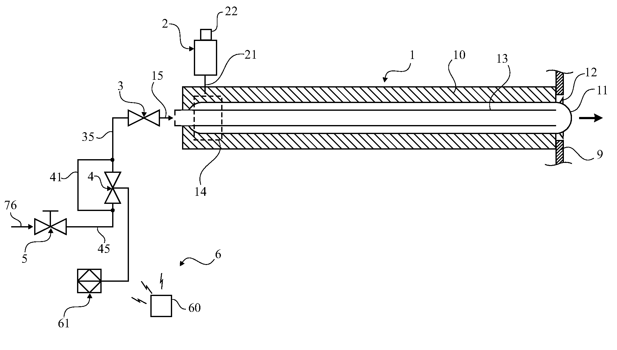
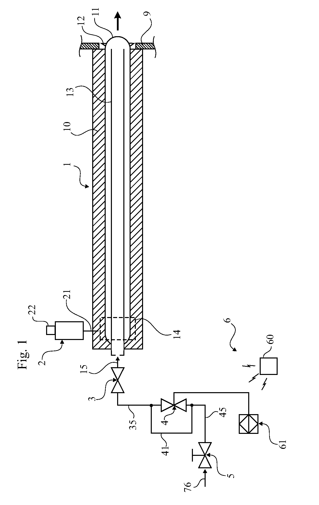
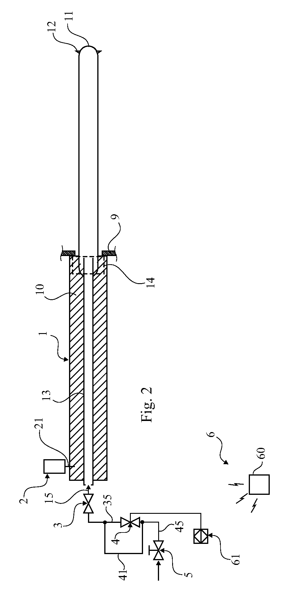
[0031]FIG. 1 schematic views of one embodiment of a sootblower arrangement 1 having a lance tube 11 retracted into an end position and just starting its insertion into the recovery furnace, the outer wall of which is designated 9. The sootblower arrangement 1 includes a frame 10, a moveable carriage 14 supported by the frame 10, and a motor 2 for moving the carriage (in a manner not shown) via a drive shaft 21. The lance tube 11 is mounted on the carriage 14 to be insertable into and retractable from the recovery furnace, and it has at least one but preferably two nozzles 12 for ejecting steam. The lance tube 11 surrounds an interior steam feed tube 13, to which an external steam feed tube 45, 35, 15 is connected for feeding sootblowing steam to be ejected through said at least one lance tube nozzle 12 into the recovery furnace. A manually operated valve 5 that normally is put in its open position, but in some situations, e.g. in connection with maintenance, may be closed. At the ou...


PUM


Abstract

This invention relates to a method of rebuilding a sootblowing system of a recovery furnace, said sootblowing system including a plurality of sootblowers (1), and each sootblower (1) including a frame (10), a moveable carriage (14) supported by the frame (10), a motor (2) for moving the carriage (14), a lance tube (11) mounted on the carriage (14) to be insertable into and retractable from the recovery furnace (8), said lance tube (11) having at least one nozzle (12), and a steam feed tube (45, 35, 15) connected to the lance tube (11) for feeding sootblowing steam to be ejected through said at least one nozzle (12) into the recovery furnace, said steam feed tube (45, 35, 15) having a first valve (3) arranged to admit steam through said at least one nozzle (12) only when the carriage with the lance tube (11) is in an activated position, i.e. during retraction and introduction of the lance tube (11), wherein further providing means (4, 30) to arrange for controlled steam supply merely during a limited time period, e.g. merely during introduction.

Description

TECHNICAL FIELD[0001]The present invention relates to a method of rebuilding a sootblowing system of a recovery furnace, said sootblowing system including a plurality of sootblowers, and each sootblower including a frame, a moveable carriage supported by the frame, a motor for moving the carriage, a lance tube mounted on the carriage to be insertable into and retractable from the recovery furnace, said lance tube having at least one nozzle, and a steam feed tube connected to the lance tube for feeding sootblowing steam to be ejected through said at least one nozzle into the recovery furnace, said steam tube having a valve for admitting steam through said at least one nozzle only when the carriage with the lance tube is moving, i.e. has left its inactive / start position. The present invention also relates to a sootblower arrangement as such and a recovery furnace including a plurality of sootblower arrangements, wherein at least one sootblower is the one referred to above.BACKGROUND A...

Claims


Application Information

Patent Timeline
Patent Type & Authority Applications(United States)
IPC IPC(8): F28G1/16F23J3/02
CPCB08B3/02B08B2230/01F28G15/04F28G1/163F23J3/02F23J3/023F28G1/166
Inventor DAHLEN, ERIKELIASSON, DANIEL
Owner SOOTTECH AB
Why Eureka
Try Eureka