Drive system of synchronous motor

a technology of synchronous motors and drive systems, applied in the direction of motor/generator/converter stoppers, dynamo-electric gear control, motor/generator/converter stoppers, etc., can solve the problems of vibration and noise, rotation pulsing, vibration and noise, and lowering detection sensitivity

Inactive Publication Date: 2010-03-18
RENESAS ELECTRONICS CORP
View PDF6 Cites 44 Cited by
  • Summary
  • Abstract
  • Description
  • Claims
  • Application Information

AI Technical Summary

Benefits of technology

[0027]Another drive system of a synchronous motor according to an typical embodiment of the present invention comprises: an inverter outputting a sine-wave AC current; a three-phase synchronous motor connected to the inverter; a first controller detecting a neutral-point potential of the three-phase synchronous motor and outputting a pulse-width modulation signal to the inverter based on a result of the detection, thereby controlling the inverter; a second controller provided with means of detecting or estimating an induced voltage of the three-phase synchronous motor and outputting a pulse-width modulation signal to the inverter based on ...

Problems solved by technology

The position detection sensitivity is lowered in the structure having low or no saliency, and the position estimation becomes difficult.
Moreover, in order to carry out the highly sensitive detection, high-frequency components to be injected have to be increased or the frequency has to be lowered, which causes rotation pulsing, vib...

Method used


Image

  • Drive system of synchronous motor
  • Drive system of synchronous motor
  • Drive system of synchronous motor

Examples


first embodiment

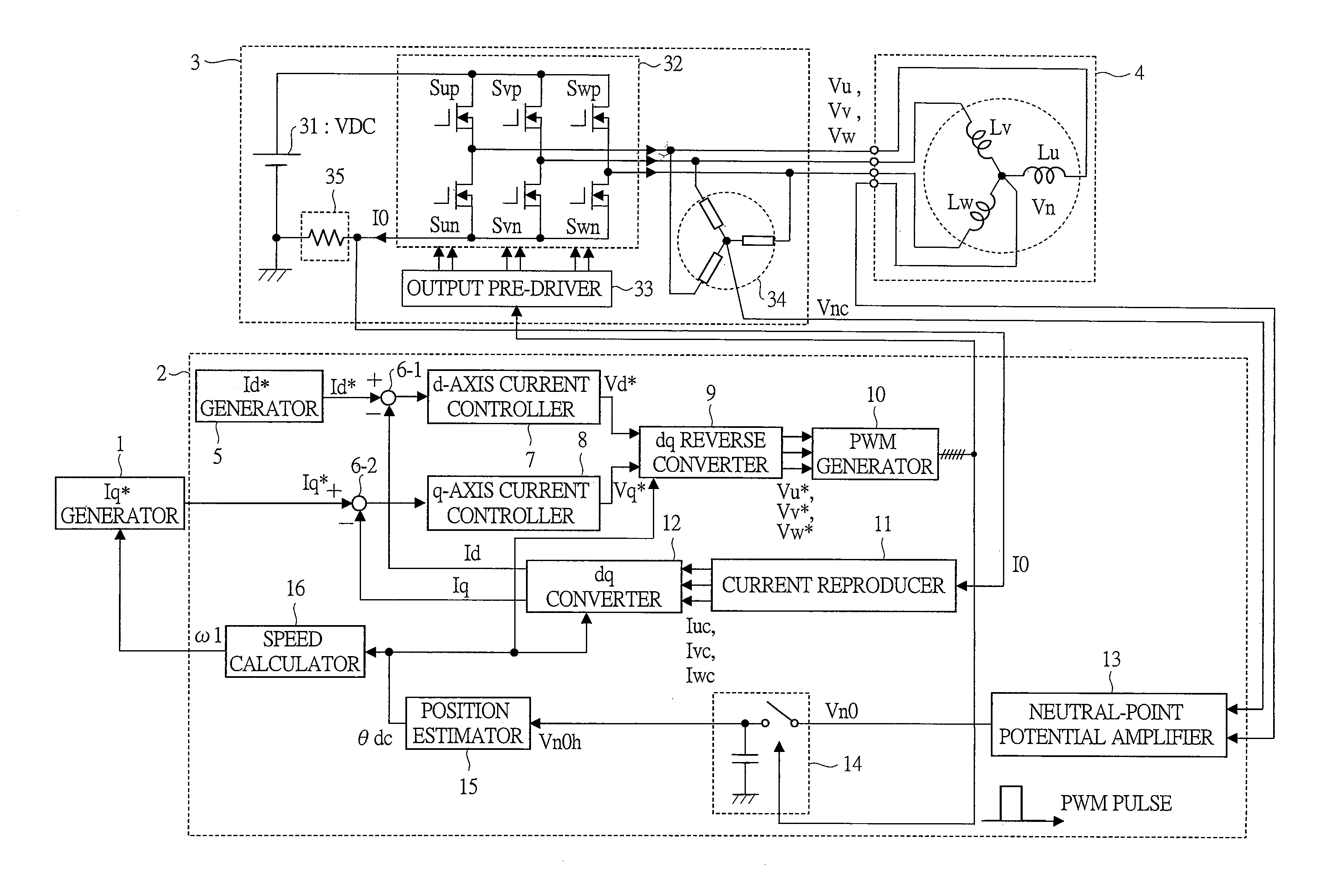
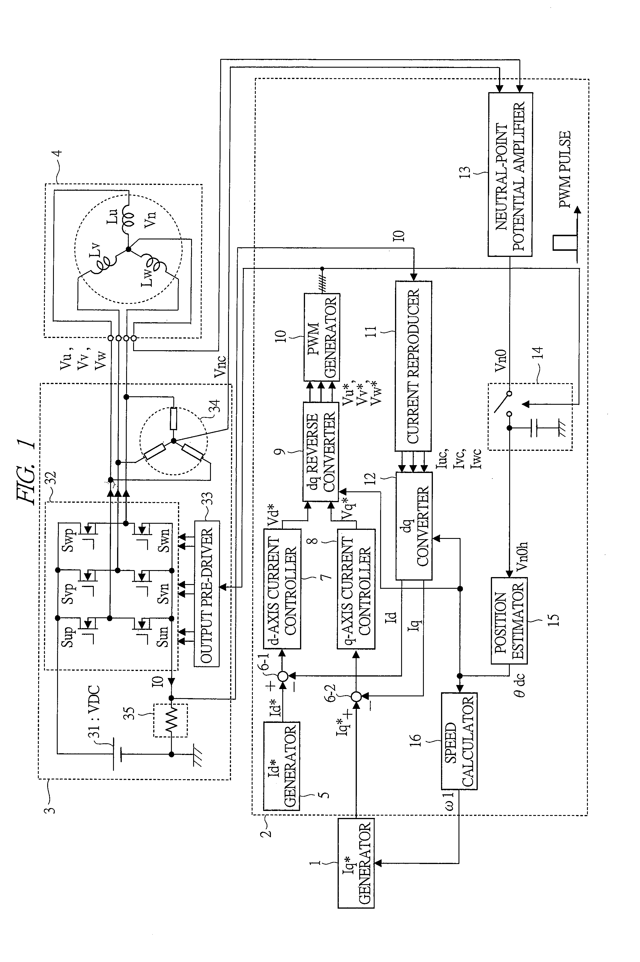
[0056]FIG. 1 is a block diagram showing a configuration of a motor drive system according to a first embodiment of the present invention.

[0057]An object of this motor drive system is to drive a permanent magnet motor (three-phase synchronous motor) 4. When roughly divided, the motor drive system comprises: an Iq* generator 1; a controller 2; an inverter 3 including an inverter main circuit 32 and a one-shunt current detector 35; and a permanent magnet motor 4 to be driven.

[0058]The Iq* generator 1 is a circuit which generates a current command Iq* corresponding to torque of a motor. The Iq* generator 1 is a controller positioned in an upper level of the controller 2. Usually, the generator has a mechanism to generate a necessary current command Iq* while observing an actual speed ω1 so that the number of rotations of the permanent magnet motor 4 reaches a predetermined speed. The current command Iq*, which is the output of the Iq* generator 1, is output to a subtractor 6-2 in the co...

second embodiment

[0113]Next, a second embodiment of the present invention will be described.

[0114]In the first embodiment, the reference level Vh is provided, this level is compared with the neutral-point potential Vn0h, and at a time when exceeding a predetermined value as a result of the comparison, the phase is updated. The reference level Vh in this case is a fixed value.

[0115]When the reference level Vh is a fixed value, the phase information is taken at every 60 degrees in terms of electrical angle, and the resolving power thereof is too low to drive the permanent magnet motor by an ideal sine-wave current. An object of the second embodiment is to solve this problem.

[0116]FIG. 9 is a block diagram showing a configuration of a position estimator 15B according to the second embodiment. In the present embodiment, the position estimator 15B is used instead of the position estimator 15 of the first embodiment.

[0117]The position estimator 15B comprises a switch 154, a first memory 155, a second memo...

third embodiment

[0123]Next, a third embodiment of the present invention will be described.

[0124]In the first and second embodiments, the PWM signal of the normal operation is used and the neutral-point potential is detected in synchronization with the PWM signal, thereby obtaining the position information. As described above, the variation of the neutral-point potential is dependent on the magnetic circuit characteristics in the permanent magnet motor 4. Therefore, the characteristics largely differ depending on specifications such as the capacity and the number of rotations of the permanent magnet motor 4. Depending on the motor structure, the case in which the detection sensitivity of the position information is insufficient is conceivable.

[0125]The present embodiment solves this problem. In the present embodiment, detection pulses of the neutral-point potential are intentionally inserted so as to create equipotential period insertion sampling periods, and the neutral-point potential is observed ...


PUM


Abstract

A position sensorless drive method capable of driving a permanent magnet motor by an ideal sine-wave current and enabling the driving from an extremely low-speed range in the vicinity of zero-speed is provided. A neutral-point potential of the permanent magnet motor is detected in synchronization with a PWM waveform of an inverter. The position of a rotor of the permanent magnet motor is estimated from the variation of the neutral-point potential. Since the neutral-point potential is varied in accordance with the magnetic circuit characteristics of an individual permanent magnet motor, the position can be detected regardless of the presence of saliency of the permanent magnet motor.

Description

CROSS-REFERENCE TO RELATED APPLICATION[0001]The present application claims priority from Japanese Patent Application No. JP 2008-237346 filed on Sep. 17, 2008, the content of which is hereby incorporated by reference into this application.TECHNICAL FIELD OF THE INVENTION[0002]The present invention relates to a technique utilized for the rotation speed control of motor drivers such as hard disk drivers (HDD), optical disk drivers, spindle motors, fans, pumps and compressors.BACKGROUND OF THE INVENTION[0003]In motor drivers such as spindle motors of HDD devices, fans and pumps, small and highly-efficient permanent magnet motors (three-phase synchronous motors) are widely used.[0004]However, in order to drive a permanent magnet motor, position information of a rotor of the motor is necessary, and therefore, a position sensor therefor has been needed. In recent years, the sensorless control, in which the number of rotations and torque of a permanent magnet motor are controlled without u...

Claims


Application Information

Patent Timeline
IPC IPC(8): H02P6/00H02P21/14H02P27/08H02P6/18H02P6/06H02P6/08H02P6/182H02P6/21H02P6/28
CPCH02P6/187H02P2207/05H02P21/04H02P21/0053H02P21/32
Inventor IWAJI, YOSHITAKAKOKAMI, YASUHIKOKUROSAWA, MINORU
Owner RENESAS ELECTRONICS CORP
Why Eureka
Try Eureka