Imaging apparatus and imaging mode control method

Inactive Publication Date: 2010-03-18
SONY CORP
View PDF12 Cites 49 Cited by
  • Summary
  • Abstract
  • Description
  • Claims
  • Application Information

AI Technical Summary

Benefits of technology

[0020]According to the embodiments of the present invention described above, the imaging mode can be switched from the normal imaging mode to the composite imaging mode under appropriate switching conditions in accordance with the shutter speed (exposure time) set variably in normal imaging mode.

Problems solved by technology

If, in such an imaging apparatus, only a fixed brightness difference is used, like in Patent Document 2, as a condition for switching from the normal imaging mode to the composite imaging mode, such a condition is not necessarily appropriate from the viewpoint of obtaining an optimum composite image.
This issue arises in an imaging system that has time limitations on the long-time exposure time and short-time exposure time when composite images are produced using two different electronic shutter speeds.

Method used


Image

  • Imaging apparatus and imaging mode control method
  • Imaging apparatus and imaging mode control method
  • Imaging apparatus and imaging mode control method

Examples


first embodiment

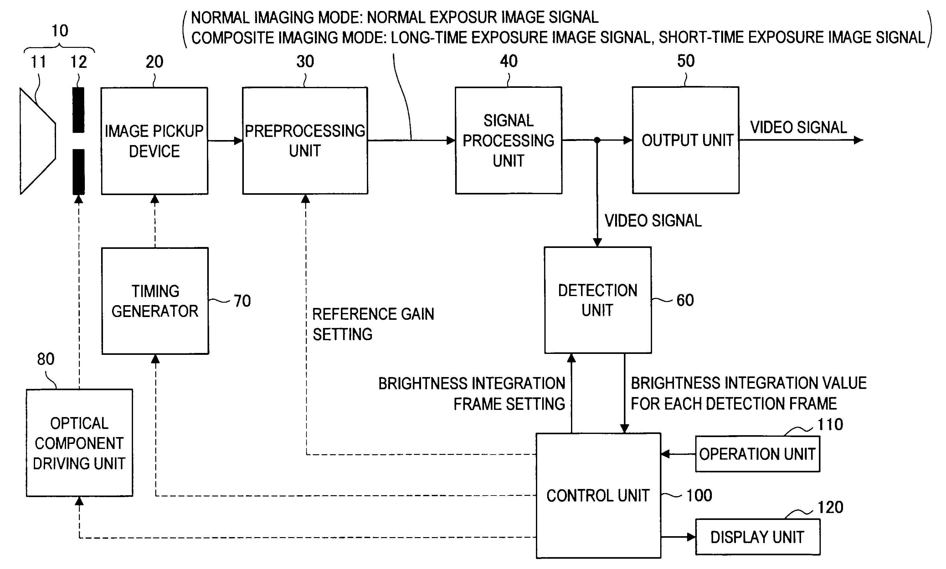
[0035]First, an imaging apparatus and an imaging method according to the first embodiment of the present invention will be described. In the description that follows, a surveillance camera capable of picking up dynamic images is taken as an example of the imaging apparatus. However, the imaging apparatus according to the first embodiment of the present invention is not limited to such an example and the present invention can be applied to any imaging device such as a digital still camera to pick up still images, digital video camera to pick up dynamic images, and mobile phone with a camera function.

[0036][1. Overview of the Imaging Mode]

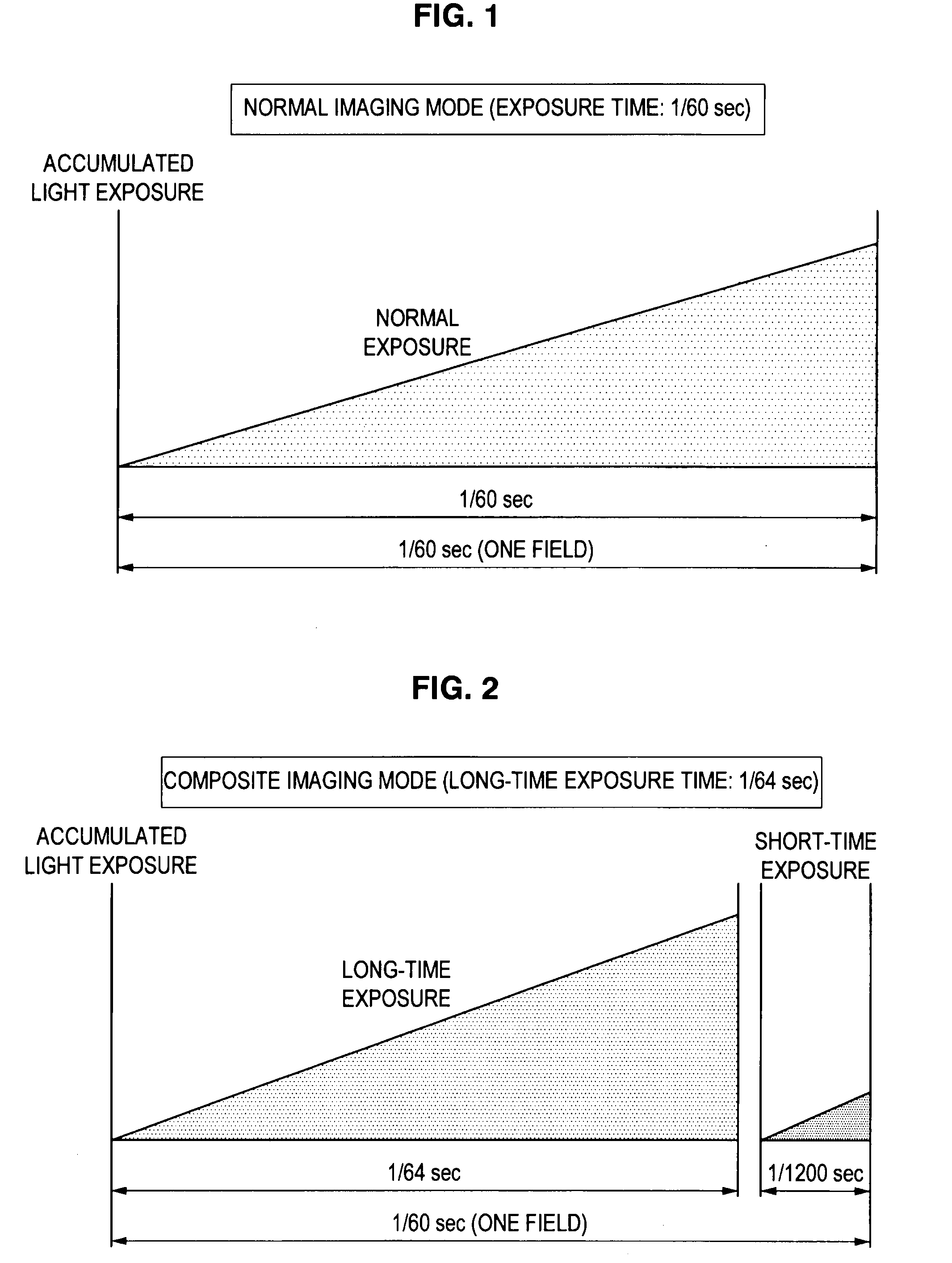
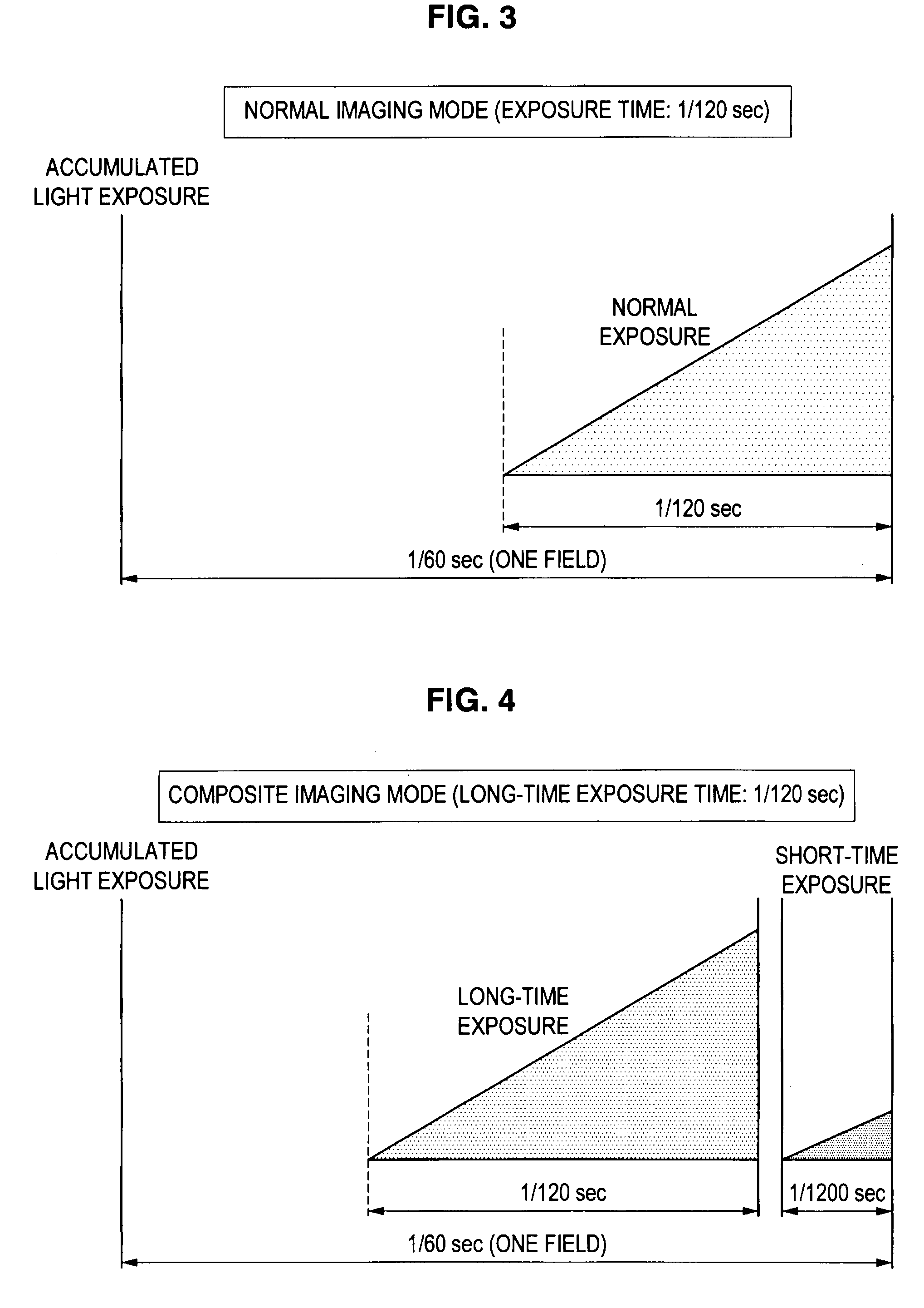
[0037]First, an overview of the imaging mode in an imaging apparatus according to the first embodiment of the present invention will be provided with reference to FIGS. 1 to 5.

[0038]An imaging apparatus in the present embodiment is a camera capable of performing an imaging operation in composite imaging mode as a wide dynamic range camera and is appl...

second embodiment

[0115]Next, an imaging apparatus and an imaging method according to the second embodiment of the present invention will be described. When compared with the first embodiment described above, the second embodiment is different in switching conditions of mode switching determination processing and the other function configuration is substantially the same as that of the first embodiment and thus, a detailed description thereof is omitted.

[0116][6. Flow of Mode Switching Determination Processing]

[0117]Next, automatic switching determination processing from the normal imaging mode to the composite imaging mode according to the second embodiment of the present invention will be described in detail with reference to FIG. 10. FIG. 10 is a flow chart showing the automatic switching determination processing of the imaging mode according to the second embodiment. The processing flow in FIG. 10 corresponds to the automatic switching determination processing (S50) of the imaging mode in FIG. 7 ...


PUM


Abstract

In an imaging apparatus capable of selectively performing an imaging operation in normal imaging mode and that in composite imaging mode, an object is imaged by performing the imaging operation in normal imaging mode to generate an exposure image signal, a brightness rate of a bright portion and dark portion of the object is calculated by detecting the exposure image signal, an exposure rate, which is a ratio of a long-time exposure time and a short-time exposure time in composite imaging mode, is calculated, and the imaging mode of the imaging apparatus is switched from the normal imaging mode to the composite imaging mode based on a comparison result of the brightness rate and the exposure rate.

Description

BACKGROUND OF THE INVENTION[0001]1. Field of the Invention[0002]The present invention relates to an imaging apparatus and an imaging mode control method.[0003]2. Description of the Related Art[0004]In an imaging apparatus in related art using a solid image pickup device such as a CCD (Charge Coupled Device), the quantity of light (light exposure) input into the image pickup device is adjusted by an aperture or electronic shutter speed. That is, when a bright scene is imaged, adjustments are made to reduce the light exposure so that so-called “overexposure” should not occur by an output signal of the image pickup device being saturated. Conversely, in a dark scene, adjustments are made to increase the light exposure so that so-called “underexposure” should not occur.[0005]However, when a scene of high contrast is imaged (for example, backlight imaging or indoor / outdoor simultaneous imaging), there arises an issue described below. That is, due to an insufficient dynamic range of the s...

Claims


Application Information

Patent Timeline
IPC IPC(8): H04N5/235
CPCH04N5/232H04N5/35581H04N5/2355H04N5/2353H04N23/60H04N23/73H04N23/741H04N25/589
Inventor ASOMA, AKIRA
Owner SONY CORP
Why Eureka
Try Eureka