Liquid crystal panel and liquid crystal display apparatus
a liquid crystal display and liquid crystal technology, applied in non-linear optics, instruments, optics, etc., can solve the problems of limited case, light leakage, light leakage, etc., and achieve the effects of enhancing viewing angle characteristics, reducing thickness, and high contras
- Summary
- Abstract
- Description
- Claims
- Application Information
AI Technical Summary
Benefits of technology
Problems solved by technology
Method used
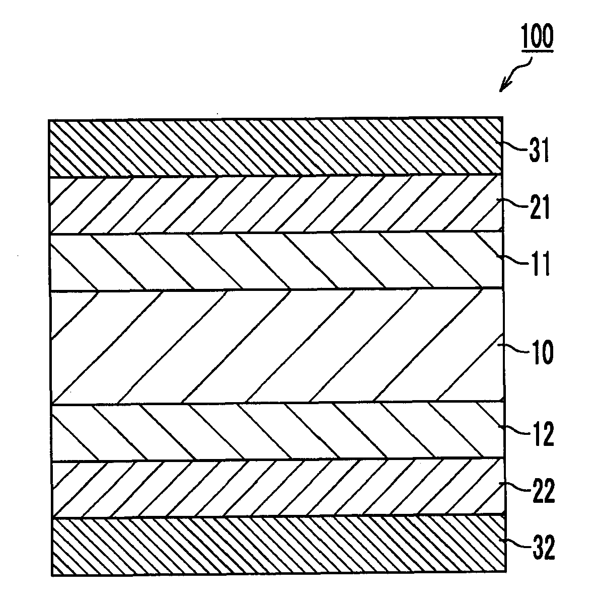
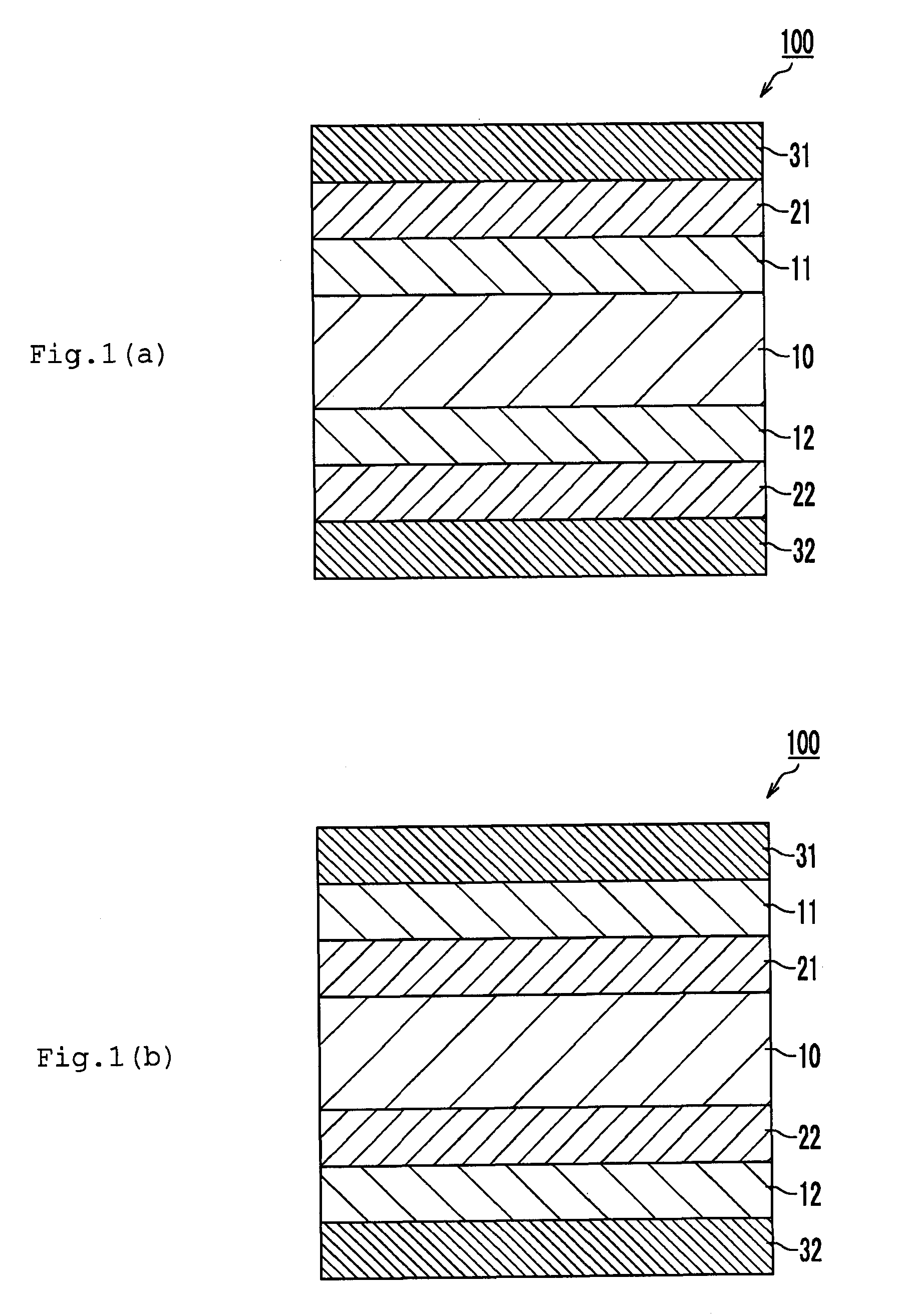
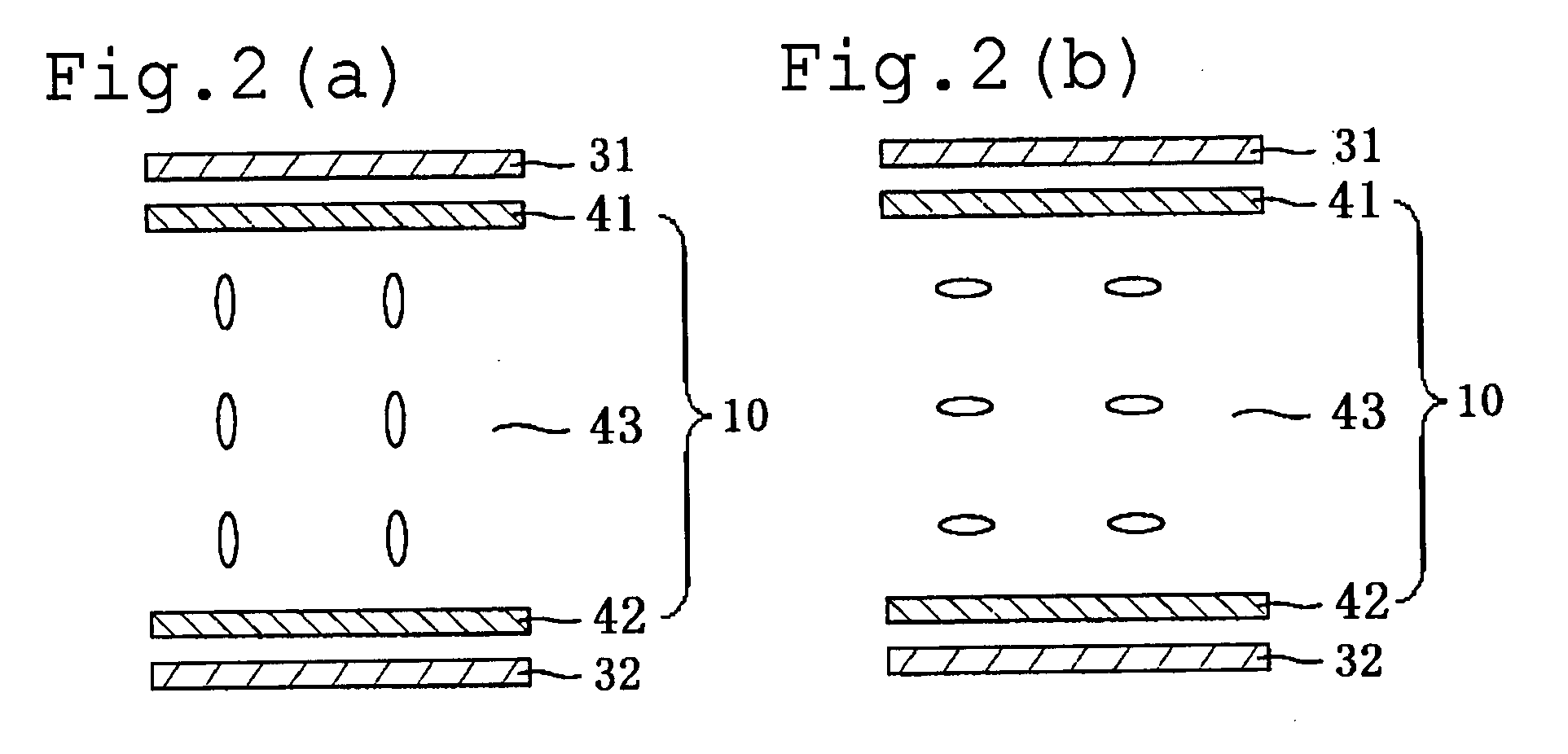
Image

Examples
example 1
Production of First Optical Compensation Layer
[0123]A film obtained by subjecting a KA film (thickness: 80 μm, manufactured by Kaneka Corporation) to fixed-end transverse stretching with stretch ratio of 2 at 150° C. was used as a first optical compensation layer. The retardation of the obtained film was measured using a retardation measurement apparatus (KOBRA21ADH manufactured by Oji Scientific Instruments Co., LTD.) to find that Re1 was 36 nm and Rth1 was 50 nm (Nz coefficient=1.4). FIG. 3(A) shows a refractive index wavelength dispersion of the film. FIG. 3 are graphs obtained by extrapolation using a Cauchy approximate expression.
[0124](Production of Second Optical Compensation Layer)
[0125]Polyimide was prepared in accordance with an established method, using 2,2′-bis(3,4-dicarboxylphenyl)hexafluoropropane (6FDA) and 2,2′-bis(trifluoromethyl)-4,4′-diaminobiphenyl(PFMB or TFMB) as starting materials. A solution prepared by dissolving the obtained polyimide in cyclohexanone so th...
example 2
Production of First Optical Compensation Layer
[0130]A film (Re1: 36 nm, Rth1: 50 nm, Nz coefficient: 1.4) produced similarly to that of Example 1 was used as a first optical compensation layer.
[0131](Production and Laminating of Second Optical Compensation Layer)
[0132]A cyclohexanone solution (15 wt %) of polyimide prepared similarly to that of Example 1 was applied to the first optical compensation layer to a thickness of 20 μm. Then, the resultant solution was dried at 100° C. for 10 minutes, whereby a laminated film in which a second optical compensation layer (polyimide film with a thickness of about 3 μm) was laminated on the first optical compensation layer was obtained. The retardation of the obtained laminated film was measured using a retardation measurement apparatus (KOBRA21ADH manufactured by Oji Scientific Instruments Co., LTD.) to find that Re was 35 nm and Rth was 155 nm.
[0133](Other Optical Elements)
[0134]As a third optical compensation layer and a fourth optical com...
example 3
[0137]The laminated film produced in Example 2 was laminated in place of a protective layer on one side of a polarizing plate (SEG1224 manufactured by Nitto Denko Corporation) via a PVA-based adhesive (thickness: 0.5 μm) so that the second optical compensation layer (fourth optical compensation layer) and the polarizing plate faced to each other and an absorption axis of a polarizer of the polarizing plate and a slow axis of the first optical compensation layer (third optical compensation layer) were perpendicular to each other. Therefore, two polarizing plates with an optical compensation layer were obtained. A liquid crystal panel was produced using the two obtained polarizing plates with an optical compensation layer, and a contrast and a color shift were measured, in the same way as in Example 1. FIG. 6 show the results.
PUM
| Property | Measurement | Unit |
|---|---|---|
| thickness direction retardation Rth | aaaaa | aaaaa |
| wavelength | aaaaa | aaaaa |
| thickness | aaaaa | aaaaa |
Abstract
Description
Claims
Application Information
PatSnap Eureka turns technology decisions into work you can execute. Powered by our Innovation Knowledge Graph, it runs expert workflows across engineering, life sciences, materials and intellectual property. Get your review-ready output in minutes.


