Load reduction dual in-line memory module (lrdimm) and method for programming the same

a memory module and dual-in-line technology, applied in the field of computers, can solve the problems of limiting the use of newer memory devices in existing computers, affecting the performance of the system, and no solution is known which would allow an lrdimm, so as to optimize the power consumption and minimize the number of dead cycles

Active Publication Date: 2010-03-18
RAMBUS INC
View PDF1 Cites 51 Cited by
  • Summary
  • Abstract
  • Description
  • Claims
  • Application Information

AI Technical Summary

Benefits of technology

[0017]The methods and apparatus of the embodiments of the invention minimize the number of dead cycles required to allow a Load Reduction DIMM (LRDIMM) to interoperate with existing Registered DIMMs (RDIMM) without making changes to existing host controllers or to the BIOS. The methods and apparatus of the embodiments of the invention also optimize power consumption incurred by on die termination of data signals on the memory bus, by allowing an unnecessary widening of the ODT windows during read and write operations to be avoided
[0047]Alternatively, or additionally, the modified parameters include a minimum column address select latency time (tAAmin), a minimum write recovery time (tWRmin), and a minimum internal write to read command delay time (tWTRmin), each parameter increased by a respective predetermined amount from corresponding values of the specification of the DRAM.

Problems solved by technology

New memory standards are often based on, and nominally compatible with, previous standards, but variations in memory bus protocol often limit the use of newer memory devices in existing computers.
Upgrades of the CPU or memory controller hosting the memory may be required, and mixing of memory types on the same memory bus is often not possible, or results in degraded performance.
Buffering in LRDIMMs results in the addition of at least one clock cycle delay in the control path (the same as in an RDIMM), but there is also delay added in the data path, which will cause a mismatch between the Data Queue Strobe (DQS) on the external memory bus, i.e. the memory bus 104, that carries the DQS signal between the host and the RDIMMs, and the strobe signal at the interface of the DRAM memory device within the LRDIMM.
But no solution is known which would allow an LRDIMM to be used with an existing host without a changed BIOS.
A major issue with integrating LRDIMMs into a memory system that also includes RDIMMs, is that all DIMMs in a system are expected to have the same latency.
The additional delay in the LRB causes a mismatch between the DQS on the memory bus and the buffered DQS at the DRAM within the LRDIMM.
It is evident that memory bus timing for LRDIMMs cannot be the same as for RDIMMs because of the added delay by the LRB in the data path.
As a result RDIMMs and LRDIMMs cannot be used in combination on the same bus.
However, this option is not readily available for existing computers that one may wish to upgrade to LRDIMMs.

Method used


Image

  • Load reduction dual in-line memory module (lrdimm) and method for programming the same
  • Load reduction dual in-line memory module (lrdimm) and method for programming the same
  • Load reduction dual in-line memory module (lrdimm) and method for programming the same

Examples


Embodiment Construction

[0076]A solution to the shortcomings of the prior art is described in the embodiments of the present invention, which aims to enable an LRDIMM work efficiently on memory busses with different clock rates, and to allow LRDIMMs to be mixed with RDIMMs on the same memory bus, even without changes to the BIOS or the memory controller.

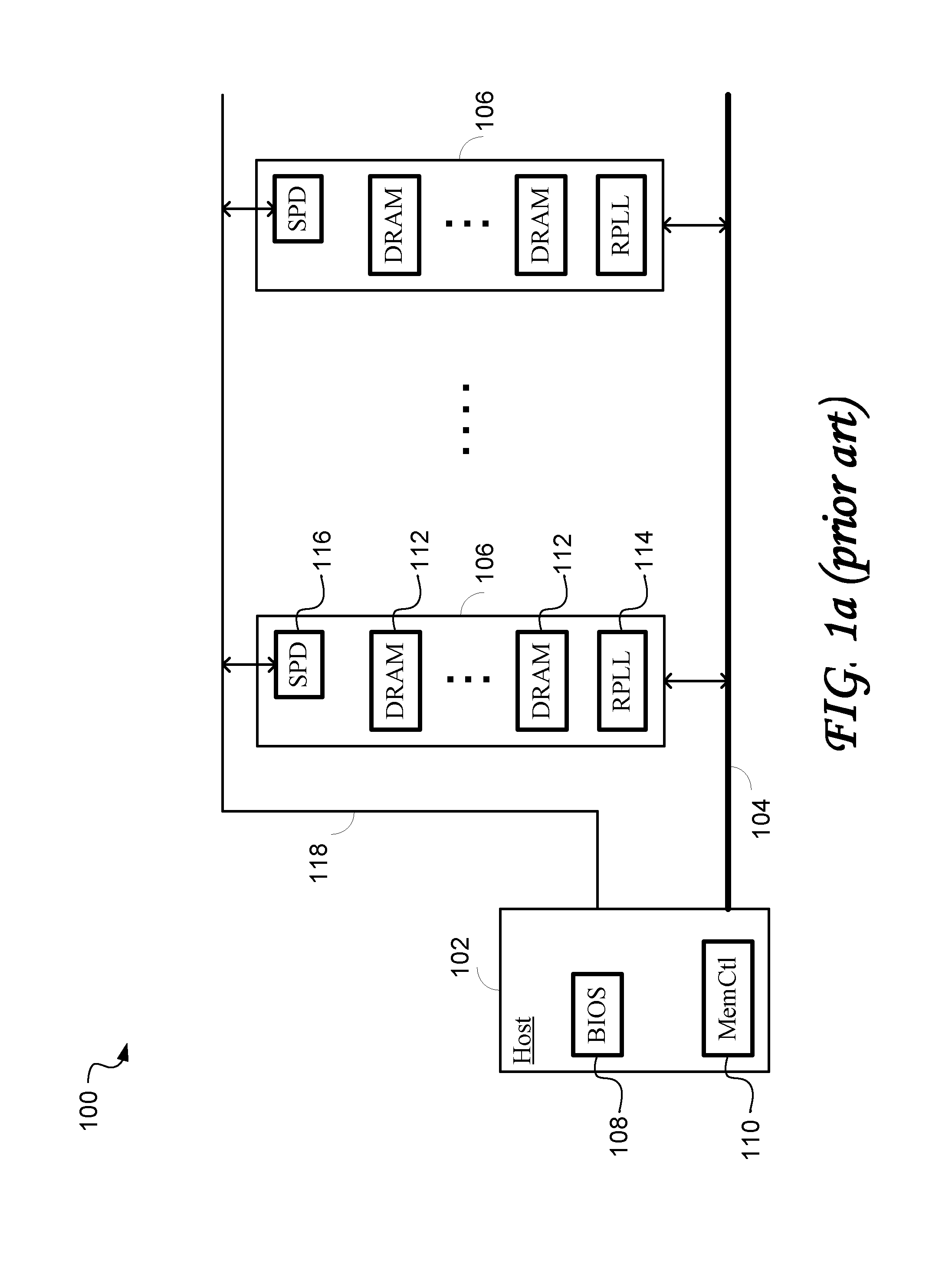
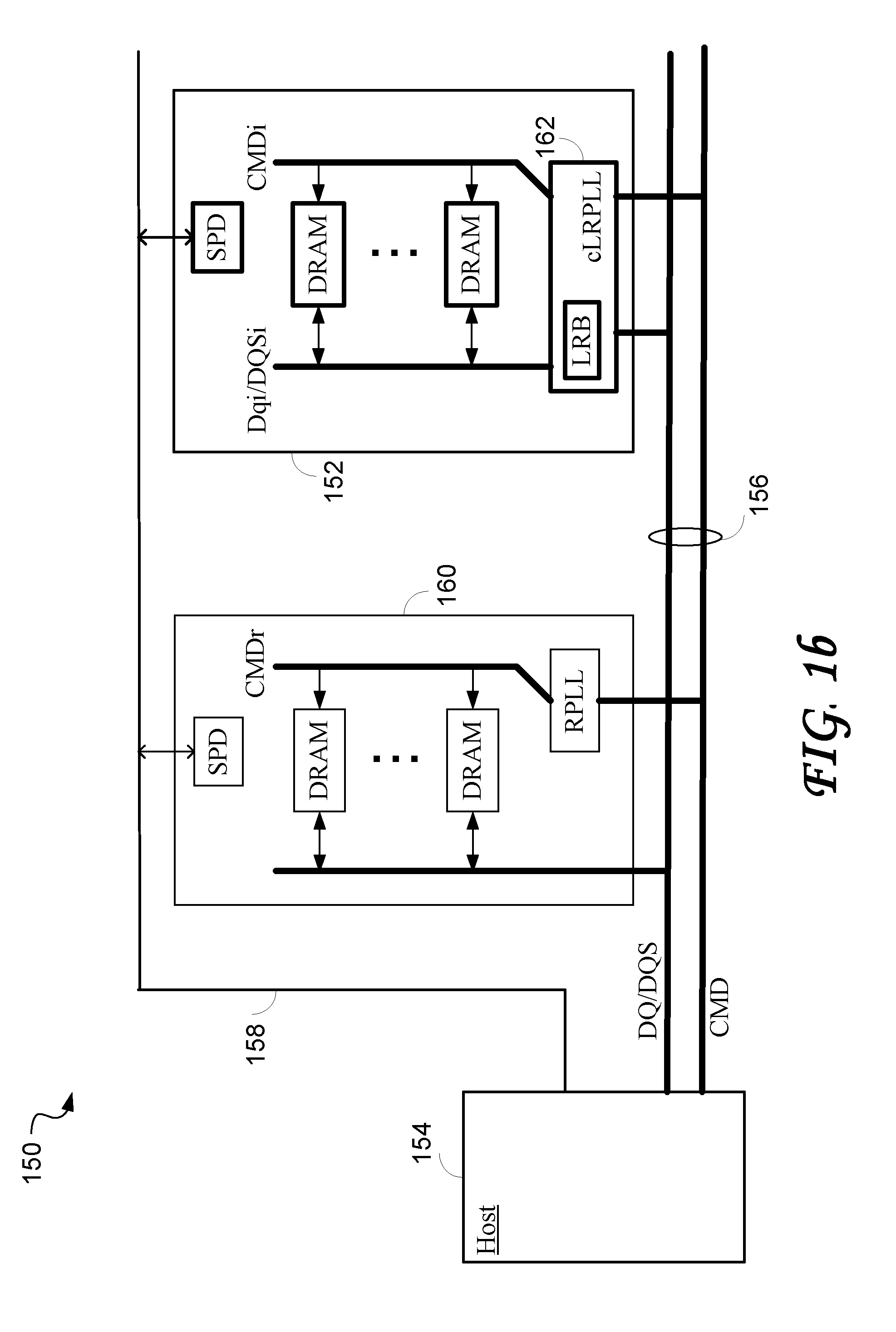
[0077]FIG. 1b shows an exemplary computer memory system 150 according to an embodiment of the invention, including at least one load reduction DIMM (LRDIMM) 152, as well as a conventional host 154, a conventional memory bus 156, a conventional system management bus (SMbus) 158, and zero or more conventional RDIMMs 160, the conventional components being equivalent to the corresponding host 102, memory bus 104, SMbus 118, and memory modules 106 of FIG. 1a.

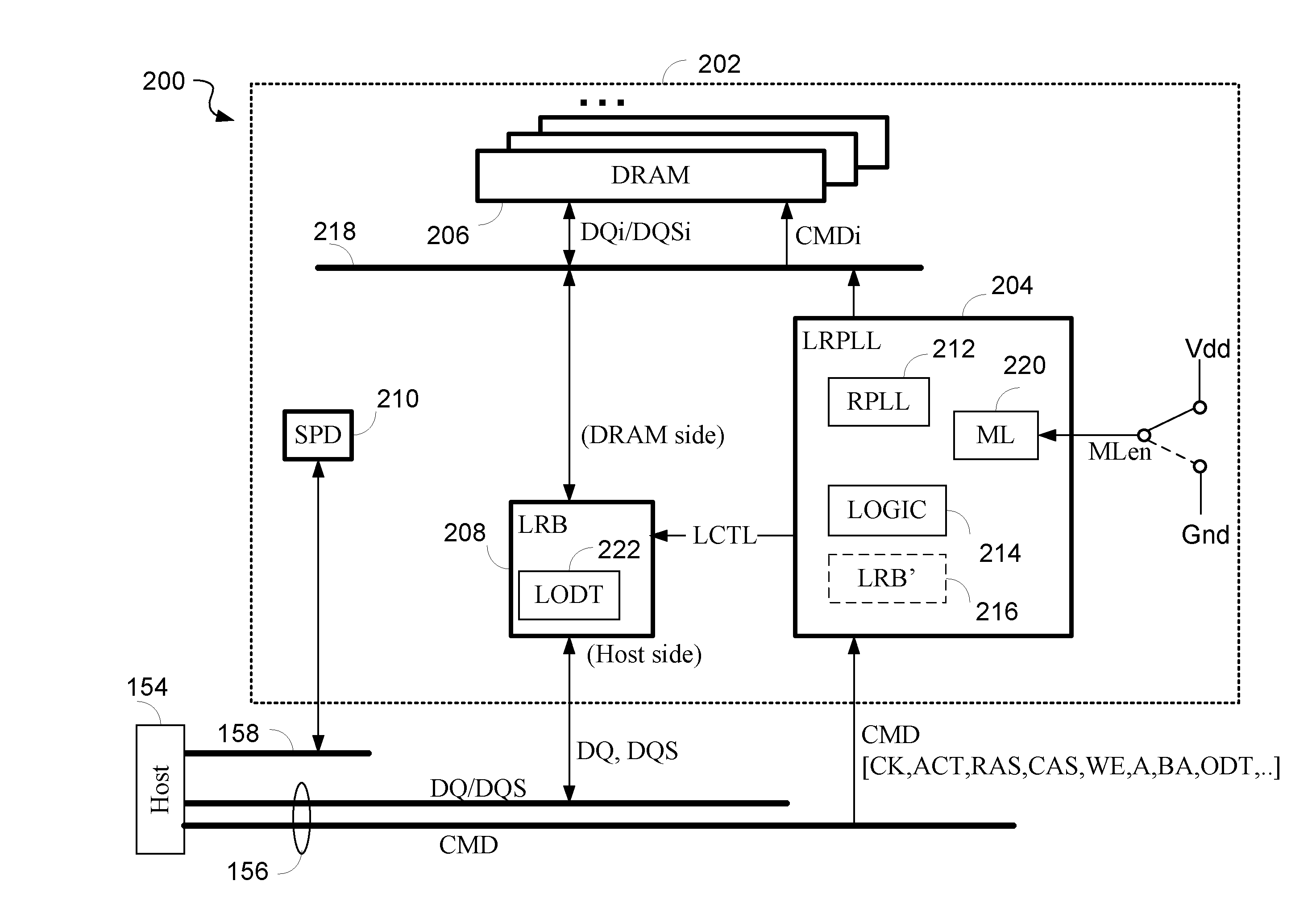
[0078]The memory bus 156 comprises a host-side command bus CMD and a host-side data bus DQ / DQS. In the conventional memory module, the host-side data bus extends directly to the memory devices (DRAMs), whil...


PUM


Abstract

A load reduction dual in-line memory module (LRDIMM) is similar to a registered dual in-line memory module (RDIMM) in which control signals are synchronously buffered but the LRDIMM includes a load reduction buffer (LRB) in the data path as well. To make an LRDIMM which appears compatible with RDIMMs on a system memory bus, the serial presence detector (SPD) of the LRDIMM is programmed with modified latency support and minimum delay values. When the dynamic read only memory (DRAMs) devices of the LRDIMM are subsequently set up by the host at boot time based on the parameters provided by the SPD, selected latency values are modified on the fly in an enhanced register phase look loop (RPLL) device. This has the effect of compensating for the delay introduced by the LRB without violating DRAM constraints, and provides memory bus timing for a LRDIMM that is indistinguishable from that of a RDIMM.

Description

RELATED APPLICATIONS[0001]The present application claims benefit from the U.S. provisional application Ser. No. 61 / 136,550 filed on Sep. 15, 2008, and U.S. provisional application Ser. No. 61 / 175,562 filed on May 5, 2009, the entire contents of both applications being incorporated herein by reference.FIELD OF THE INVENTION[0002]The present invention relates in general to the field of computers, and in particular, to memory devices. Still more particularly, the present invention is related to a method and apparatus for enabling interoperation of registered dual in-line memory modules (RDIMMs) and load reduction dual in-line memory modules (LRDIMMs).BACKGROUND OF THE INVENTION[0003]The memory technology of computers has continuously been evolving in the interest of increased capacity as well as speed. New memory standards are often based on, and nominally compatible with, previous standards, but variations in memory bus protocol often limit the use of newer memory devices in existing ...

Claims


Application Information

Patent Timeline
Patent Type & Authority Applications(United States)
IPC IPC(8): G06F12/00G06F15/177G06F12/02
CPCG11C7/1051G11C7/1057G11C7/1072G11C11/4093G11C8/18G06F3/0661G06F3/0611G06F3/0673
Inventor AMER, MAHERTAKEFMAN, MICHAEL LEWIS
Owner RAMBUS INC
Why Eureka
Try Eureka