Method and apparatus for calibrating mass flow controllers

Inactive Publication Date: 2010-03-25
APPLIED MATERIALS INC
View PDF7 Cites 23 Cited by
  • Summary
  • Abstract
  • Description
  • Claims
  • Application Information

AI Technical Summary

Benefits of technology

[0007]Embodiments of the present invention comprise a method for determining the flow rate of a gas provided to a process chamber. In some embodiments, a method for determining the flow rate of a gas includes measuring a first concentration of a calibration gas provided to the process chamber at a first pressure and temperature by directing infrared radiation into the process chamber and monitoring a first amount of infrared radiation absorbed by the calibration gas. A mixture of a second gas and the calibration gas is provided to the process chamber while maintaining the first pressure and temperature. A second concentration of the calibration gas in the mixture is measured by directing infrared radiation into the process chamber and monitoring a second amount of infrared radiation absorbed by the calibration gas. A flow rate of the second gas is calculated by comparing the first and second concentrations of the calibration gas. In some embodiments, the calibration gas and the second gas may not absorb the infrared radiation at the same wavelength.
[0008]In some embodiments, a method for calibrating a plurality of mass flow controllers provided to a plurality of process chambers includes providing a single infrared radiation source to a plurality of process chambers, each process chamber having one or more mass flow controllers. At least one of the one or more mass flow controllers of each process chamber may be calibrated by measuring a first concentration of a calibration gas provided to the process chamber at a constant pressure and temperature by directing infrared radiation into each process chamber and monitoring a first amount of infrared radiation absorbed by the calibration gas. A mixture of a desired gas a

Problems solved by technology

Unfortunately, the calibration process can only be performed to an uncertainty of about 5% for each mass flow controller, which may be too imprecise for future processing.
In addition, the calibration of the mass flow controllers drift over time, leading to process variation.
Furthermore, the standard mass flow controller also drifts over time, which can further result in inaccurate calibrations.

Method used


Image

  • Method and apparatus for calibrating mass flow controllers
  • Method and apparatus for calibrating mass flow controllers
  • Method and apparatus for calibrating mass flow controllers

Examples


Embodiment Construction

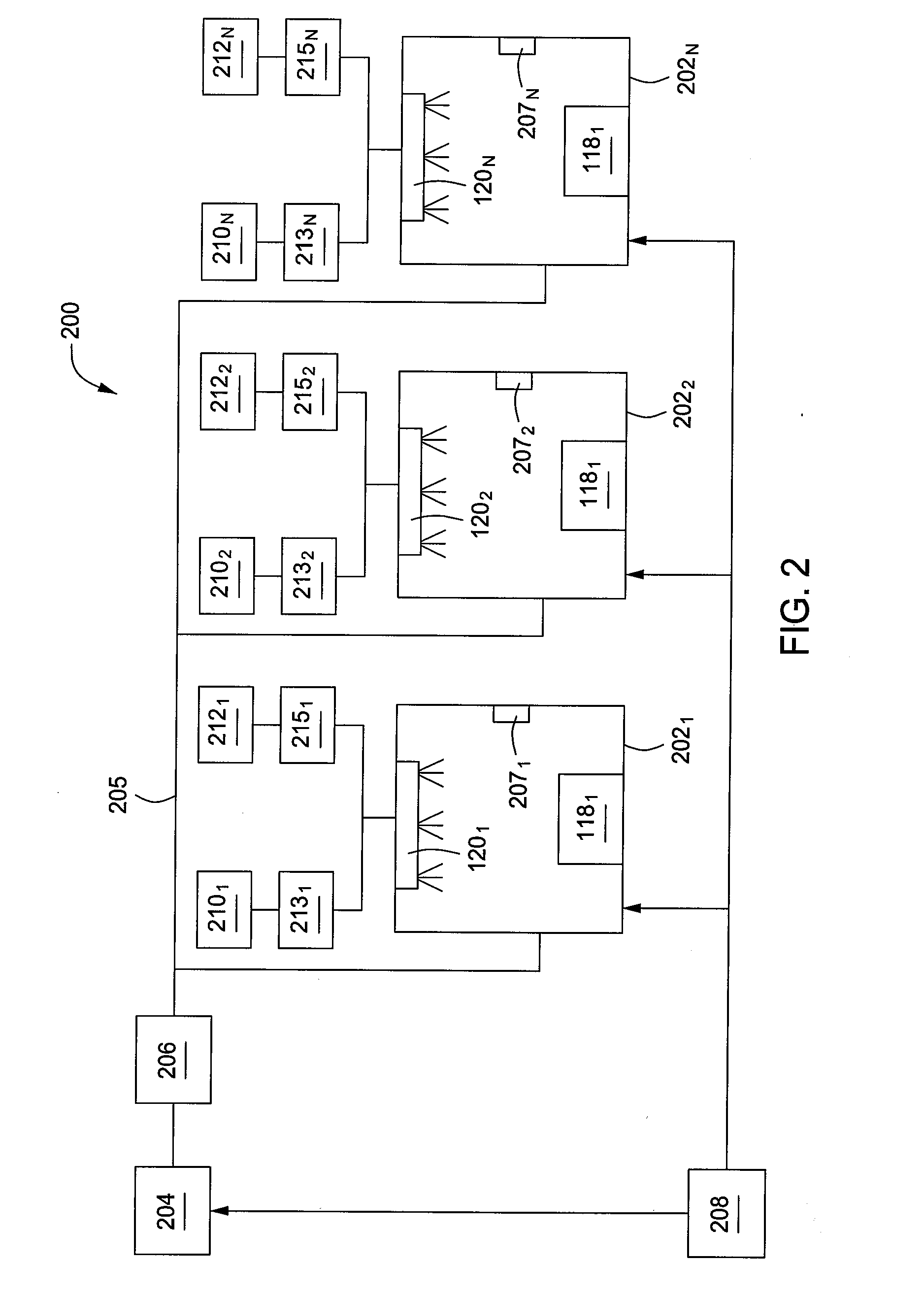
[0016]Embodiments of methods and apparatus for calibrating mass flow controllers are provided herein. In some embodiments, the inventive methods may include using infrared (IR) radiation to calibrate one or more mass flow controllers coupled to a semiconductor process chamber. In some embodiments, the inventive methods may be further applied to one or more process chambers using either a serial or parallel process to calibrate the mass flow controllers coupled to each process chamber. The inventive methods and apparatus may advantageously provide improved calibration of mass flow controllers. In some embodiments, the inventive methods and apparatus may advantageously provide calibration of mass flow controllers to an accuracy of within about 1%.

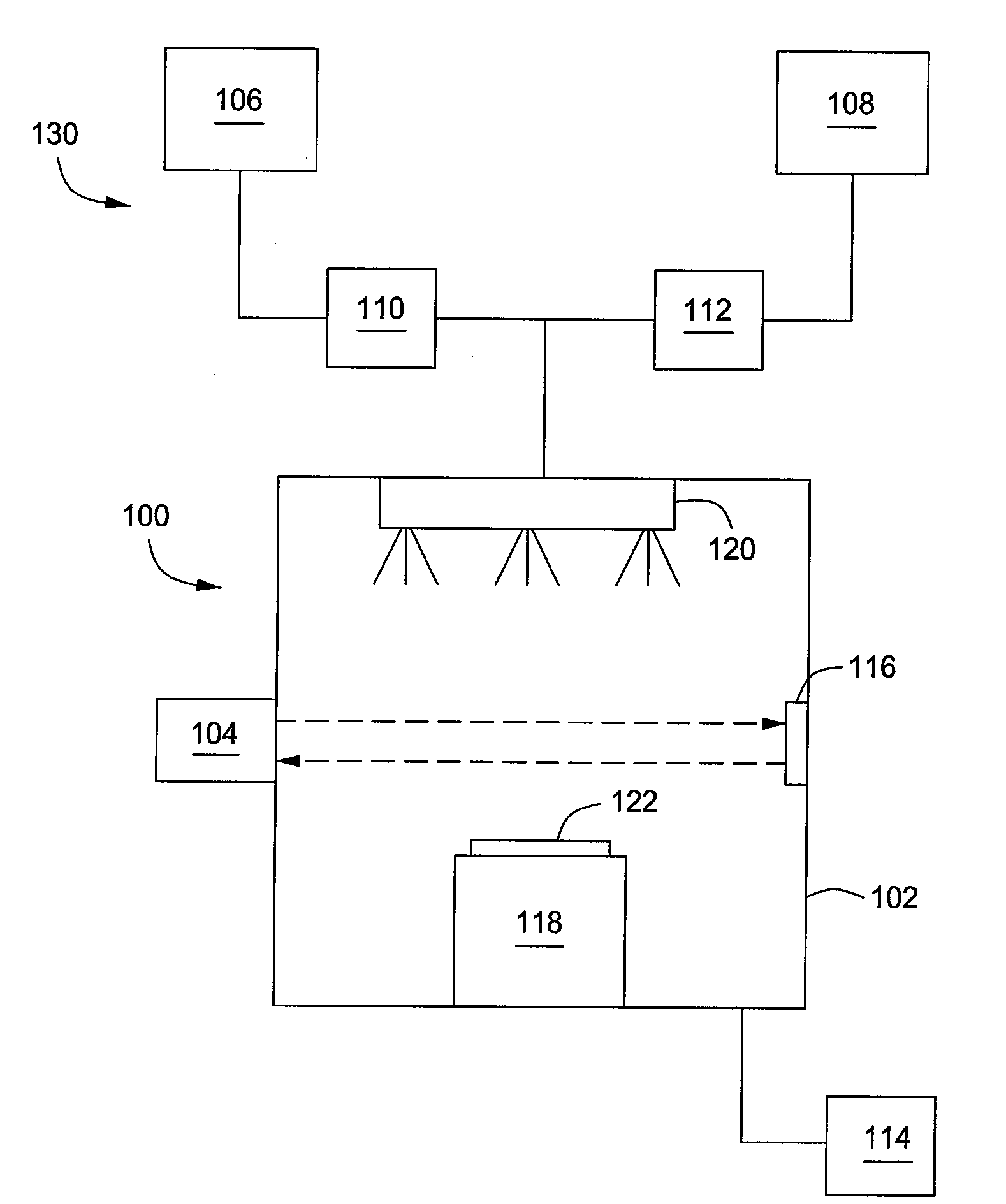
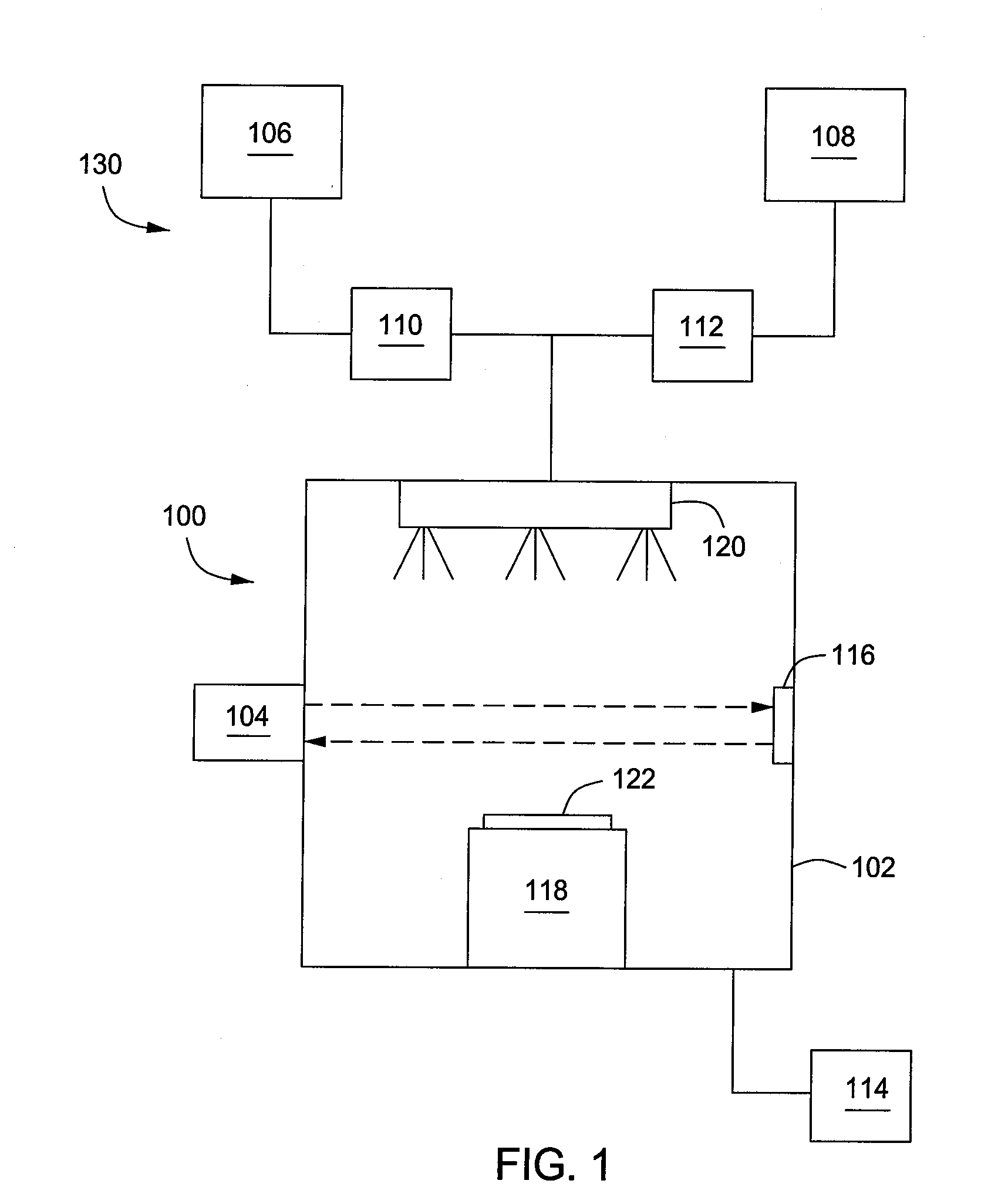
[0017]FIG. 1 depicts a schematic view of an apparatus 100 for calibrating mass flow controller in accordance with some embodiments of the present invention. The apparatus 100 may include a process chamber 102, an IR radiation apparatus 104, a...


PUM

PropertyMeasurementUnit
Temperatureaaaaaaaaaa
Pressureaaaaaaaaaa
Flow rateaaaaaaaaaa

Abstract

A method for determining the flow rate of a gas includes measuring a first concentration of a calibration gas provided to the process chamber at a first pressure and temperature by directing infrared radiation into the process chamber and monitoring a first amount of infrared radiation absorbed by the calibration gas. A mixture of a second gas and the calibration gas is provided to the process chamber while maintaining the first pressure and temperature. A second concentration of the calibration gas in the mixture is measured by directing infrared radiation into the process chamber and monitoring a second amount of infrared radiation absorbed by the calibration gas. A flow rate of the second gas is calculated by comparing the first and second concentrations of the calibration gas. In one embodiment, the calibration gas and the second gas may not absorb the infrared radiation at the same wavelength.

Description

BACKGROUND[0001]1. Field[0002]Embodiments of the present invention generally relate to semiconductor processing equipment and more particularly, to methods and apparatus for calibration of mass flow controllers.[0003]2. Description of the Related Art[0004]Continued reduction in size of semiconductor devices is dependent upon more precise control of, for instance, the flow rate of process gases delivered to a semiconductor process chamber in which such semiconductor devices are processed. Typically, the process gases are provided utilizing a mass flow controller for each process gas being delivered to the chamber.[0005]To maintain precise control, the mass flow controllers must provide an accurate and repeatable operation. Therefore, the mass flow controllers are periodically calibrated, for example, every few weeks. Typically, a calibration process may involve individually comparing the flow rate from each mass flow controller to that of a standard mass flow controller (e.g., a mass...

Claims


Application Information

Patent Timeline
IPC IPC(8): G01F25/00C23F1/08
CPCG01F25/0007G01F1/667G01F25/10
Inventor DAVIS, MATTHEW F.LILL, THORSTEN B.WALKER, QUENTIN E.
Owner APPLIED MATERIALS INC
Why Eureka
Try Eureka