
Resonator and crankcase ventilation system for internal combustion engine

Active Publication Date: 2010-03-25
GM GLOBAL TECH OPERATIONS LLC
View PDF8 Cites 27 Cited by
  • Summary
  • Abstract
  • Description
  • Claims
  • Application Information

AI Technical Summary

Benefits of technology

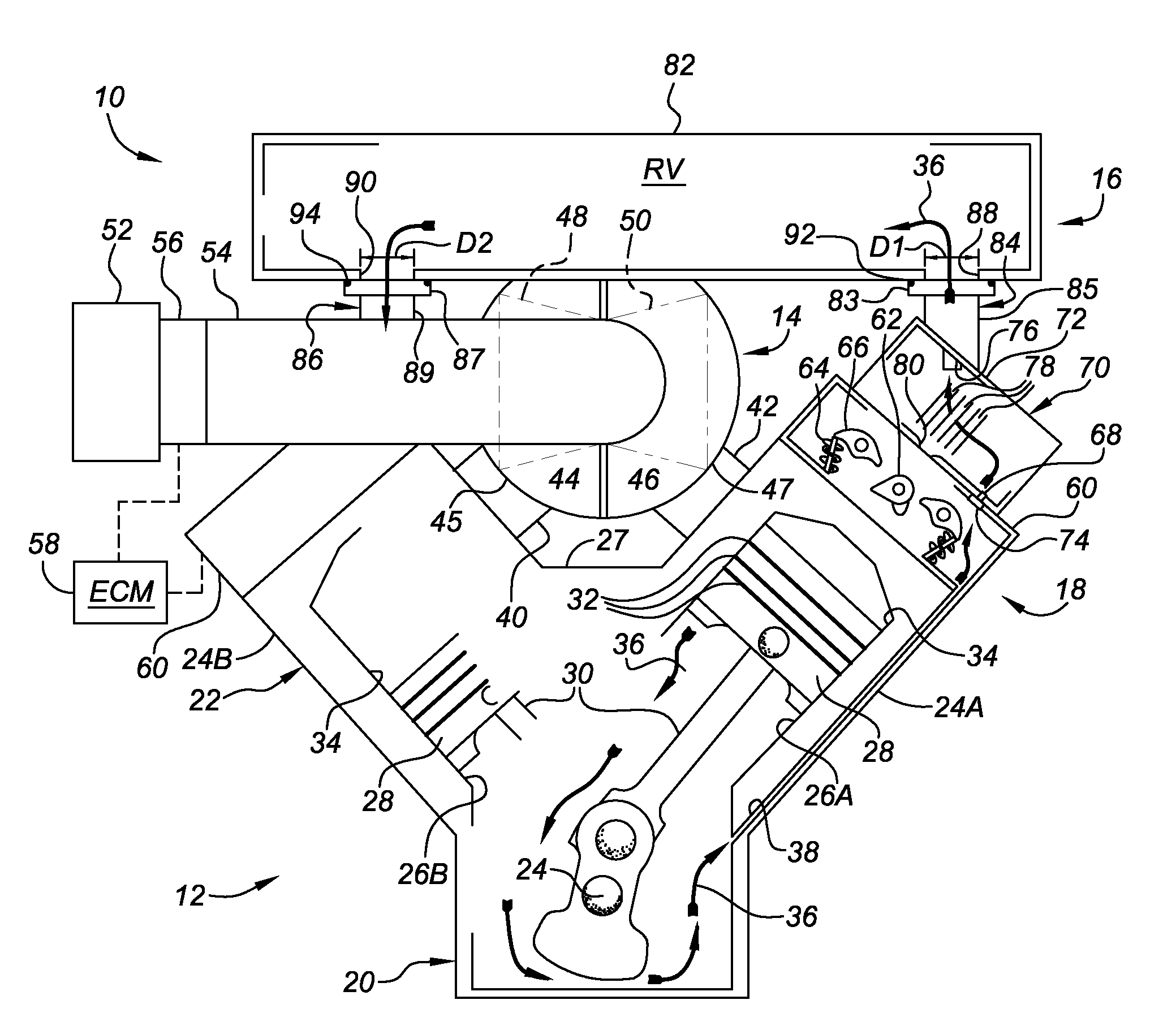
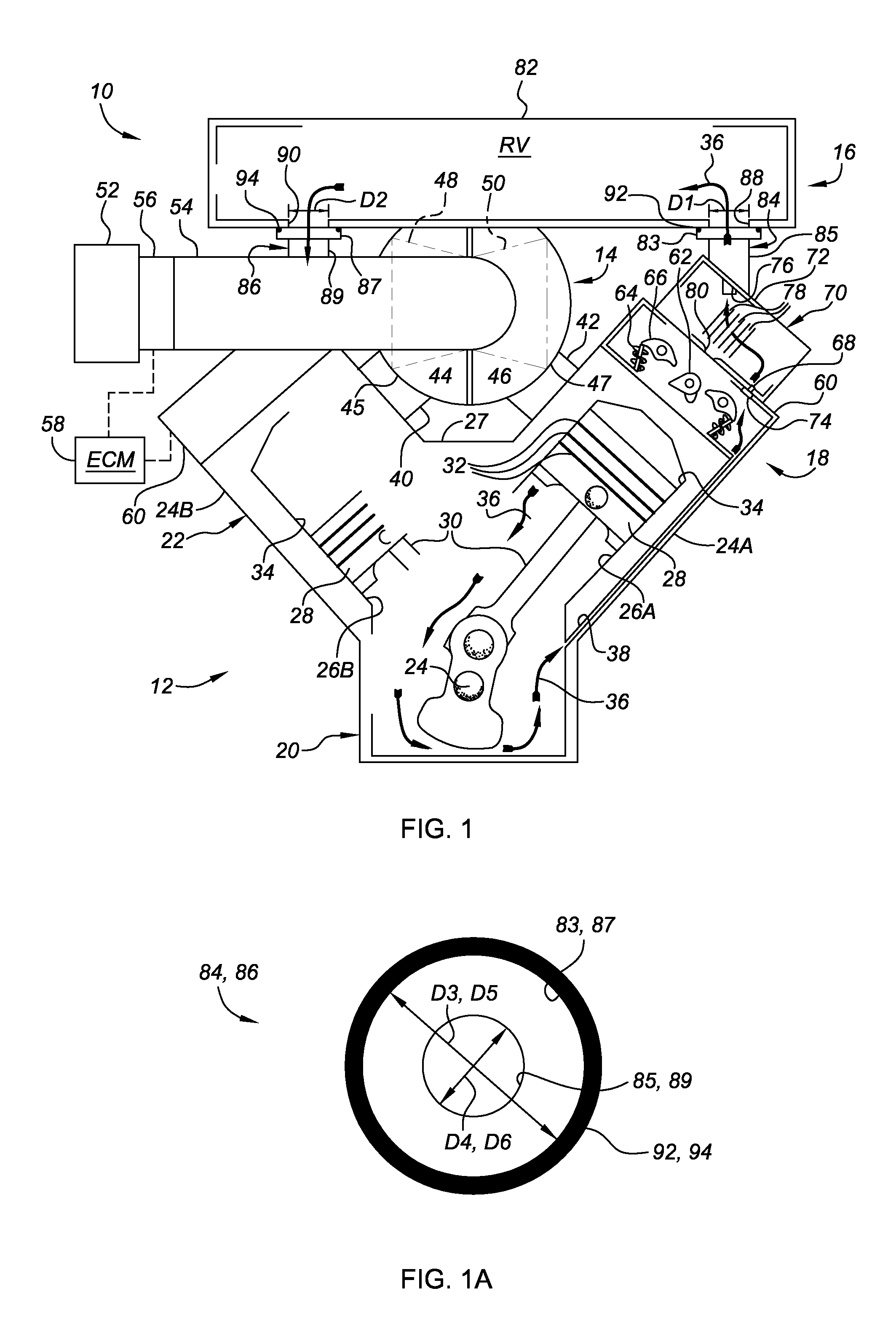
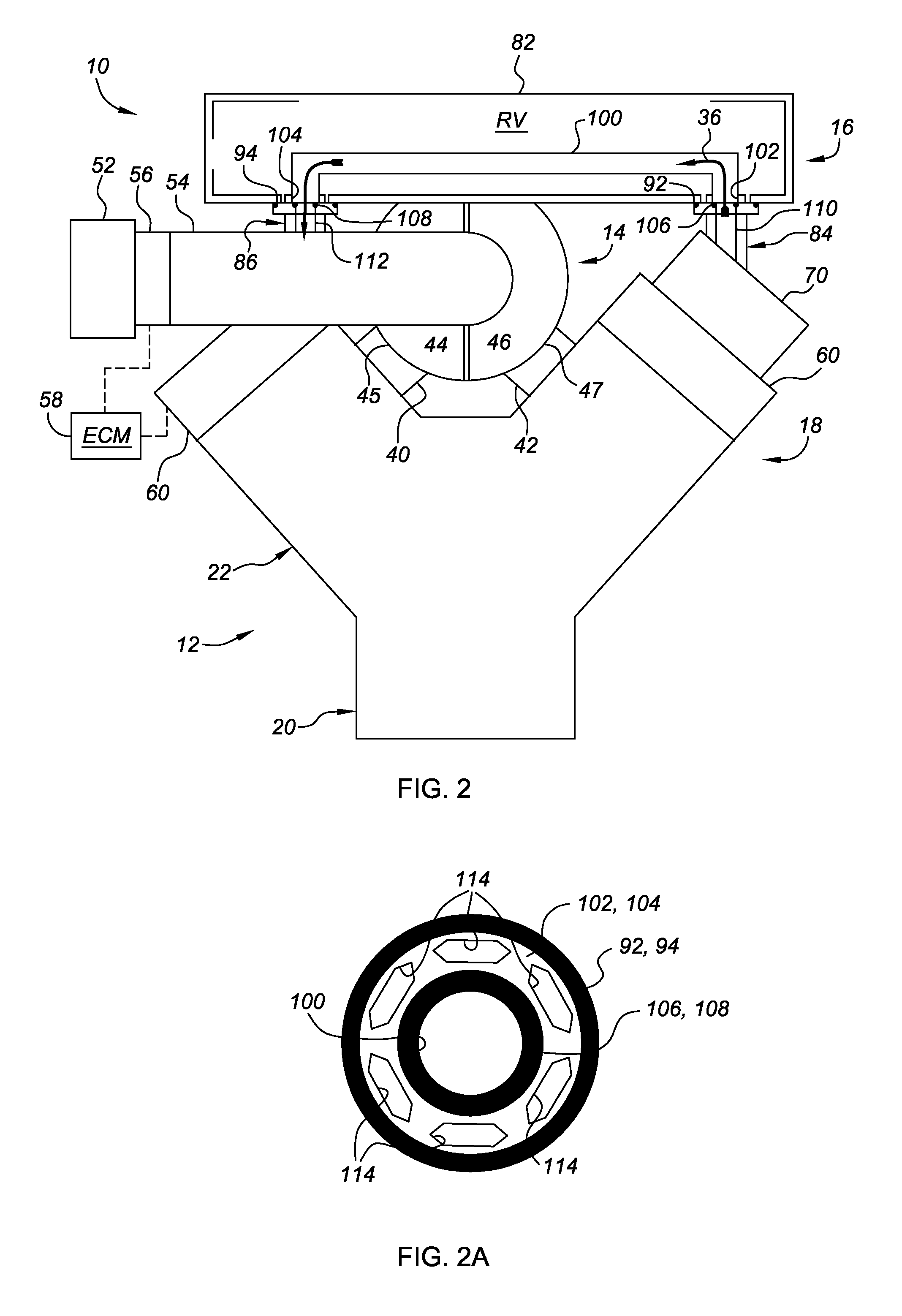
[0008]According to one embodiment of the present invention, an internal combustion engine (ICE) assembly may be provided. The ICE assembly includes an engine block having a crankcase portion that is adjacent to a cylinder case portion. The cylinder case portion defines one or more cylinder bores therein. An air intake system is in fluid communication with the cylinder bore(s), and configured to selectively deliver air charges thereto. A valve cover, which may consist of a cam cover or rocker cover, is operatively attached to the engine block. The valve cover is in fluid communication with the crankcase portion of the engine block to receive blowby gases therefrom. The ICE assembly also includes a sound dissipating resonator that has a resonator body which defines a resonator volume therein. The resonator body, which may be positively attached to the engine block, fluidly communicates the valve cover with the engine air intake system, whereby blowby gases are delivered or evacuated from the valve cover through the resonator volume to the air intake system. Integration of the blowby passage into the resonator reduces the number of potential leak paths in the air induction system, and reduces overall engine mass, cost, and packaging size.
[0010]According to another aspect, the resonator body defines a fluid inlet port having a first diameter, and a fluid outlet port having a second diameter. In this regard, a first connection neck is in fluid communication between the inlet port and the valve cover. The first connection neck has a third diameter that is greater than the first diameter of the resonator inlet port. In addition, a second connection neck is in fluid communication between the outlet port and air intake system. The second connection neck has a fourth diameter that is greater than the second diameter of the resonator outlet port. First and second annular seal members respectively fluidly seal the connections between the first and second connection necks and the fluid inlet and outlet ports. By providing enlarged flow areas at the resonator inlet port—i.e., the connection between the oil separation unit and resonator body, and at the resonator outlet port—i.e., the connection between the resonator body and the turbocharger air inlet pipe, the present design offers improved On-board Diagnostics (OBD) by allowing only large flow areas to be disconnected for which leakage is easier to diagnose due to the increased leak rate.

Problems solved by technology

Excessive blowby gas may result in reduced cylinder compression, as well as oil contamination and dilution.

Method used


Image

  • Resonator and crankcase ventilation system for internal combustion engine
  • Resonator and crankcase ventilation system for internal combustion engine
  • Resonator and crankcase ventilation system for internal combustion engine

Examples


Embodiment Construction

[0022]Referring to the drawings, wherein like reference numbers refer to like components throughout the several views, there is shown a schematic illustration of a representative internal combustion engine (ICE) assembly with which the present invention may be incorporated and practiced. It should be readily understood that the ICE assembly illustrated herein is merely provided as an exemplary application by which the present invention may be utilized. As such, the present invention is by no means limited to the particular engine configuration shown in the drawings. In addition, the ICE assembly illustrated herein has been greatly simplified, it being understood that further information regarding the standard operation of an internal combustion engine, whether it be spark ignited or compression ignited, may be found in the prior art. Finally, the drawings presented herein are not to scale and are provided purely for instructional purposes. Thus, the individual and relative dimension...


PUM


Abstract

The present invention provides a crankcase ventilation system and resonator for a turbocharged internal combustion engine assembly. The resonator, designed for intake noise reduction, is mounted to the engine. An oil separation unit, designed for passage of blowby gases, is mounted to a cam cover, sandwiched between the resonator and cam cover. The resonator has a resonator body defining a resonator volume therein. The resonator fluidly communicates the oil separation unit with the turbocharger air inlet pipe, whereby blowby gases are evacuated from the cam cover and delivered through the resonator volume for reintroduction to the engine's air intake system. Integration of the blowby passages into the resonator reduces the number of potential leak paths in the air induction system, and reduces overall engine mass, cost, and packaging size. The present design also offers improved On-board Diagnostics (OBD) by allowing only large flow areas to be disconnected.

Description

TECHNICAL FIELD[0001]The present invention relates generally to internal combustion engines, and more specifically to internal combustion engine assemblies equipped with a resonator and a crankcase ventilation system with oil separation unit.BACKGROUND OF THE INVENTION[0002]“V-type” internal combustion engine (ICE) assemblies are traditionally defined by an engine block having a pair of outwardly angled cylinder banks with inside walls that define an interbank valley therebetween. Each cylinder bank of a typical V-type, over-head valve internal combustion engine assembly defines one or more cylinder bores each having a piston reciprocally movable therein. The piston and cylinder bore cooperate with a portion of a cylinder head, which is generally attached to the top face of the cylinder bank, to form a variable volume combustion chamber.[0003]The cylinder head defines intake ports through which air, provided by an intake manifold, is selectively introduced into the combustion chambe...

Claims


Application Information

Patent Timeline
IPC IPC(8): F01M13/04F02M35/12
CPCF01M13/022F01M13/0405F02M25/06F02M35/1255F02M35/10222Y02T10/121Y02T10/144F02M35/10157Y02T10/12
Inventor ARVAN, GARY J.
Owner GM GLOBAL TECH OPERATIONS LLC
Learn More