Ceramic discharge chamber for a discharge lamp

a discharge lamp and ceramic technology, applied in the field of lighting, can solve the problems of depletion of filler constituents, certain reactive properties of fused quartz, and high operating temperature, and achieve the effects of reducing the number of potential bond defects, facilitating the assembly of the chamber, and reducing the number of bonds

Inactive Publication Date: 2007-11-20
GENERAL ELECTRIC CO
View PDF30 Cites 4 Cited by
  • Summary
  • Abstract
  • Description
  • Claims
  • Application Information

AI Technical Summary

Benefits of technology

[0014]The members which form the ceramic discharge chamber can greatly facilitate assembly of the chamber, because the discharge chamber can be constructed with only one or two bonds between the members. The reduction in the number of bonds also has the advantages of reducing the number of potential bond defects during manufacturing, and reducing the possibility of breakage of the discharge chamber at a bond region during handling. One or more of the members may also include a radially directed flange which allows the members to be precisely aligned during assembly to improve the quality of the lamp.
[0015]Exemplary embodiments of the invention can be used to improve the performance of various types of lamps, such as metal halide lamps, high pressure mercury vapor lamps, high pressure sodium vapor lamps, and white high pressure sodium lamps.

Problems solved by technology

Fused quartz, however, has certain disadvantages which arise from its reactive properties at high operating temperatures.
For example, in a quartz lamp, at temperatures greater than about 950-1000° C., the halide filling reacts with the glass to produce silicates and silicon halide, which results in depletion of the filler constituents.
Elevated temperatures also cause sodium to permeate through the quartz wall, which causes depletion of the filler.
Both depletions cause color shift over time, which reduces the useful lifetime of the lamp.
Although quartz lamps can be operated below 950° C. for increased lifetime, the quality of the light produced is compromised, because the light properties produced by the lamp depend on the operating temperature of the discharge chamber.
For example, the number of component parts is relatively large and introduces a corresponding number of opportunities for variation and defects.
Also, the conventional discharge chamber includes four bonding regions, each of which introduces an opportunity for lamp failure by leakage of the filler material if the bond is formed improperly.
Each bonding area also introduces a region of relative weakness, so that even if the bond is formed properly, the bond may break during handling or be damaged enough in handling to induce failure in operation.
Another disadvantage relates to the precision with which the parts can be assembled and the resulting effect on the light quality.
The number of parts shown in FIGS. 1a-1e makes it difficult to consistently achieve a gap size within an acceptable tolerance without significant effort devoted to optimizing the manufacturing process.

Method used


Image

  • Ceramic discharge chamber for a discharge lamp
  • Ceramic discharge chamber for a discharge lamp
  • Ceramic discharge chamber for a discharge lamp

Examples


Embodiment Construction

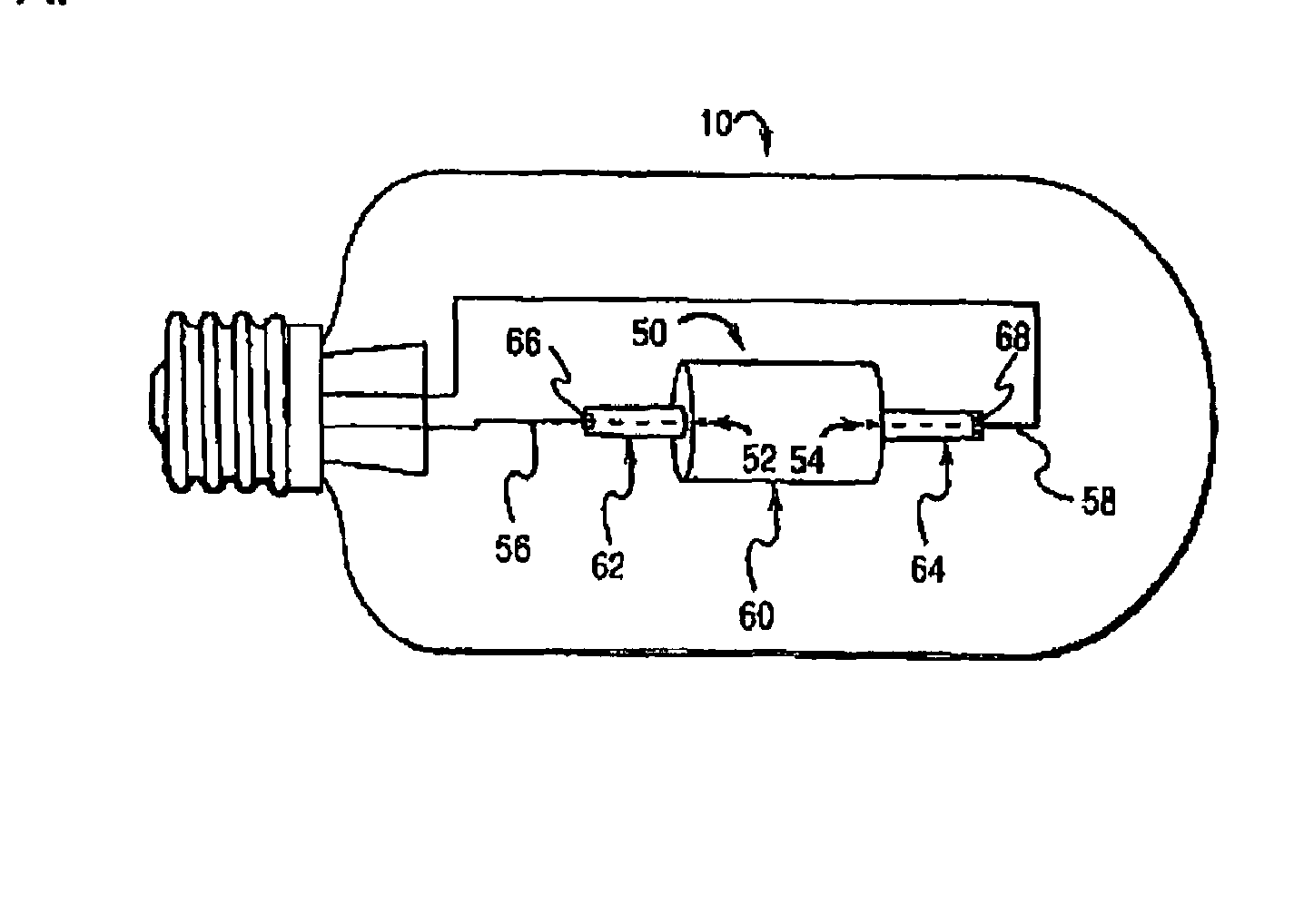
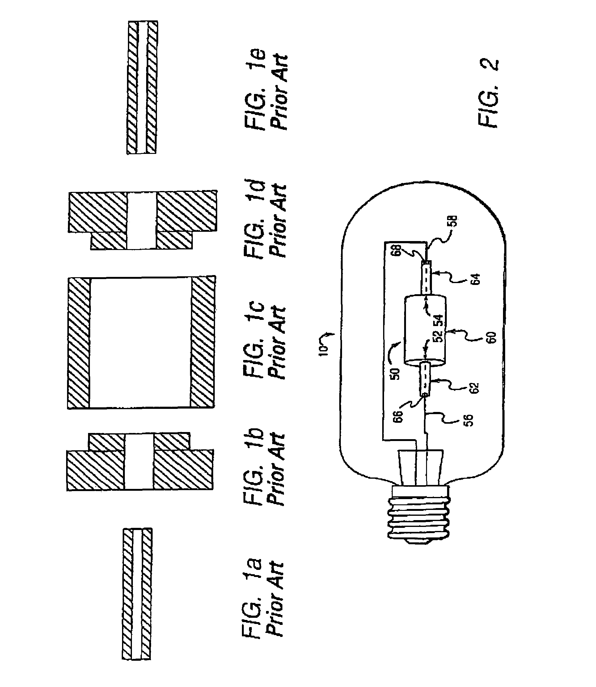
[0020]FIG. 2 illustrates a discharge lamp 10 according to an exemplary embodiment of the invention The discharge lamp 10 includes a discharge chamber 50 which contains two electrodes 52, 54 and a filler material. The electrodes 52, 54 are connected to conductors 56, 58 which apply a potential difference across the electrodes. In operation, the electrodes 52, 54 produce an arc which ionizes the filler material to produce a plasma in the discharge chamber 50. The emission characteristics of the light produced by the plasma depend primarily on the constituents of the filler material, the voltage across the electrodes, the temperature distribution of the chamber, the pressure in the chamber, and the geometry of the chamber. For a ceramic metal halide lamp, the filler material typically comprises a mixture of Hg, a rare gas such as Ar or Xe, and a metal halide such as NaI, lII, or DyI3. For a high pressure sodium lamp, the filler material typically comprises Na, a rare gas, and Hg. Other...


PUM

PropertyMeasurementUnit
angleaaaaaaaaaa
temperaturesaaaaaaaaaa
temperatureaaaaaaaaaa

Abstract

A ceramic discharge chamber for a lamp, according to an exemplary embodiment of the invention, comprises a first member which includes a leg portion and a transition portion, wherein the leg portion and the transition portion are integrally formed as one piece from a ceramic material, and a second member which includes a body portion, wherein the body portion is bonded to the transition portion of the first member. The ceramic discharge chamber can be formed by injection molding a ceramic material to form the first member, the first member forming a first portion of the ceramic discharge chamber; and bonding the first member to a second member which forms a second portion of the ceramic discharge chamber.

Description

[0001]This application is a division of application Ser. No. 10 / 408,609, filed Apr. 7, 2003 now U.S. Pat. No. 6,791,266, which is hereby incorporated by reference in its entirety.[0002]This application is a continuation-in-part of U.S. Ser. No. 09 / 067,816, filed Apr. 28, 1998, which is hereby incorporated by reference in its entirety.BACKGROUND[0003]1. Field of the Invention[0004]The present invention relates generally to lighting, and more particularly to a ceramic discharge chamber for a discharge lamp, such as a ceramic metal halide lamp.[0005]2. Description of the Related Art[0006]Discharge lamps produce light by ionizing a filler material such as a mixture of metal halides and mercury with an electric arc passing between two electrodes. The electrodes and the filler material are sealed within a translucent or transparent discharge chamber which maintains the pressure of the energized filler material and allows the emitted light to pass through it. The filler material, also know...

Claims


Application Information

Patent Timeline
Patent Type & Authority Patents(United States)
IPC IPC(8): H01J9/00H01J17/16H01J17/18H01J61/36H01J9/24H01J61/30
CPCH01J61/30H01J9/247
Inventor VENKATARAMANI, VENKAT SUBRAMANIAMGRESKOVICH, CHARLES DAVIDSCOTT, CURTIS EDWARDBREWER, JAMES ANTHONY
Owner GENERAL ELECTRIC CO
Why Eureka
Try Eureka