
Actuator for generating a rotational positioning movement

a technology of rotational positioning and actuator, which is applied in the direction of gearing, transportation and packaging, hoisting equipment, etc., can solve the problems of low peak current consumption of electric motor, unfavorable efficiency and self-locking, and achieve high positioning speed

Inactive Publication Date: 2010-03-25
ZF FRIEDRICHSHAFEN AG
View PDF15 Cites 38 Cited by
  • Summary
  • Abstract
  • Description
  • Claims
  • Application Information

AI Technical Summary

Benefits of technology

[0005]The object of the present invention is therefore to create an actuator for generating rotational positioning movements which is suitable for the cramped installation conditions of a vehicle and has a high positioning speed.
[0007]In order to achieve an increase in the positioning speed of the actuator considering the installation conditions prevailing in a vehicle, like limited voltage, current and installation space, the masses mobilized in the reduction gear have to be reduced and the efficiency of the reduction gear has to be increased, and the positioning forces acting against the actuator have to be utilized for which reason the reduction gear according to the present invention is designed such, that it is not self-locking. Since a single reduction gear of the harmonic, cycloidal or wobble type has a comparatively large diameter for the gear ratio required for generating the required torque, has no acceptable efficiency and is self-locking from experience, and unadulterated stepped, planetary or Wolfrom gears have too-large a mass inertia, the reduction gear of the actuator according to the present invention comprises two component assemblies. The first assembly comprises a single-step harmonic, cycloidal or wobble gear, and the second assembly comprises a single-step or multistep planetary, stepped or Wolfrom gear. Both assemblies are interconnected such, that the required total gear ratio results from a high efficiency and a compact installation space, and the reduction gear is simultaneously not self-locking. Compared to an unadulterated planetary, stepped or Wolfrom gear, the reduction gear has low complexity and inertia, resulting in a drop in the peak current consumption of the electric motor. As a result, it may be designed with a smaller size which allows a further reduction in the required installation space.
[0008]An embodiment of the present invention provides, that the first assembly is arranged between the electric motor and the second assembly, whereby the first assembly, i.e. the harmonic, cycloidal of wobble gear, is arranged on the side of the reduction gear having the lower torque. Since the torque placed on the first assembly is consequently reduced, it can be designed more compact, i.e. the diameter of the first assembly may be considerably reduced. It is especially advantageous, if the gear ratio of the first assembly is below 1:40, as higher gear ratios in practice cause unfavorable efficiency and self-locking. In addition, it is advantageous, if the second assembly comprises at least one planet carrier, at least one sun gear and, if necessary, at least one ring gear, whereby one of the planet carriers or one of the ring gears serves as a preferred output element of the reduction gear, from which the rotational movements can be tapped.
[0009]A preferred application of the actuator according to the present invention provides, that it is used as part of a vehicle stabilizer bar which is divided in two parts and electromechanically adjustable for roll stabilization or ride height control. For roll stabilization, a single actuator according to the present invention is inserted between both parts of the vehicle stabilizer bar, as a result of which in case of rolling movement, both parts may rotate against one another such that they generate movement in the opposite direction of the rolling movement thus attenuating or eliminating the rolling movement. In an especially preferred embodiment of the present invention a first part of the vehicle stabilizer bar is connected stationary to the output element of the reduction gear of the actuator, and a second part of the vehicle stabilizer bar is connected to the actuator case.

Problems solved by technology

Compared to an unadulterated planetary, stepped or Wolfrom gear, the reduction gear has low complexity and inertia, resulting in a drop in the peak current consumption of the electric motor.
It is especially advantageous, if the gear ratio of the first assembly is below 1:40, as higher gear ratios in practice cause unfavorable efficiency and self-locking.

Method used


Image

  • Actuator for generating a rotational positioning movement
  • Actuator for generating a rotational positioning movement
  • Actuator for generating a rotational positioning movement

Examples


Embodiment Construction

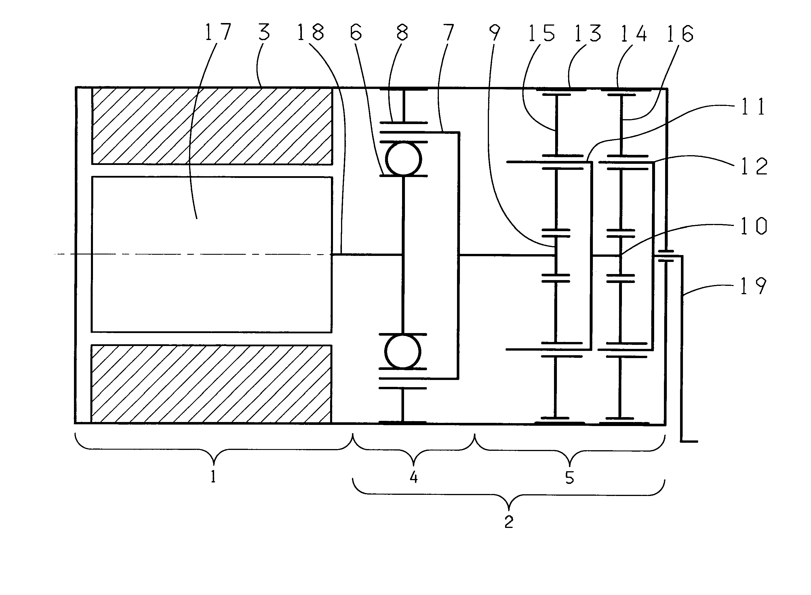
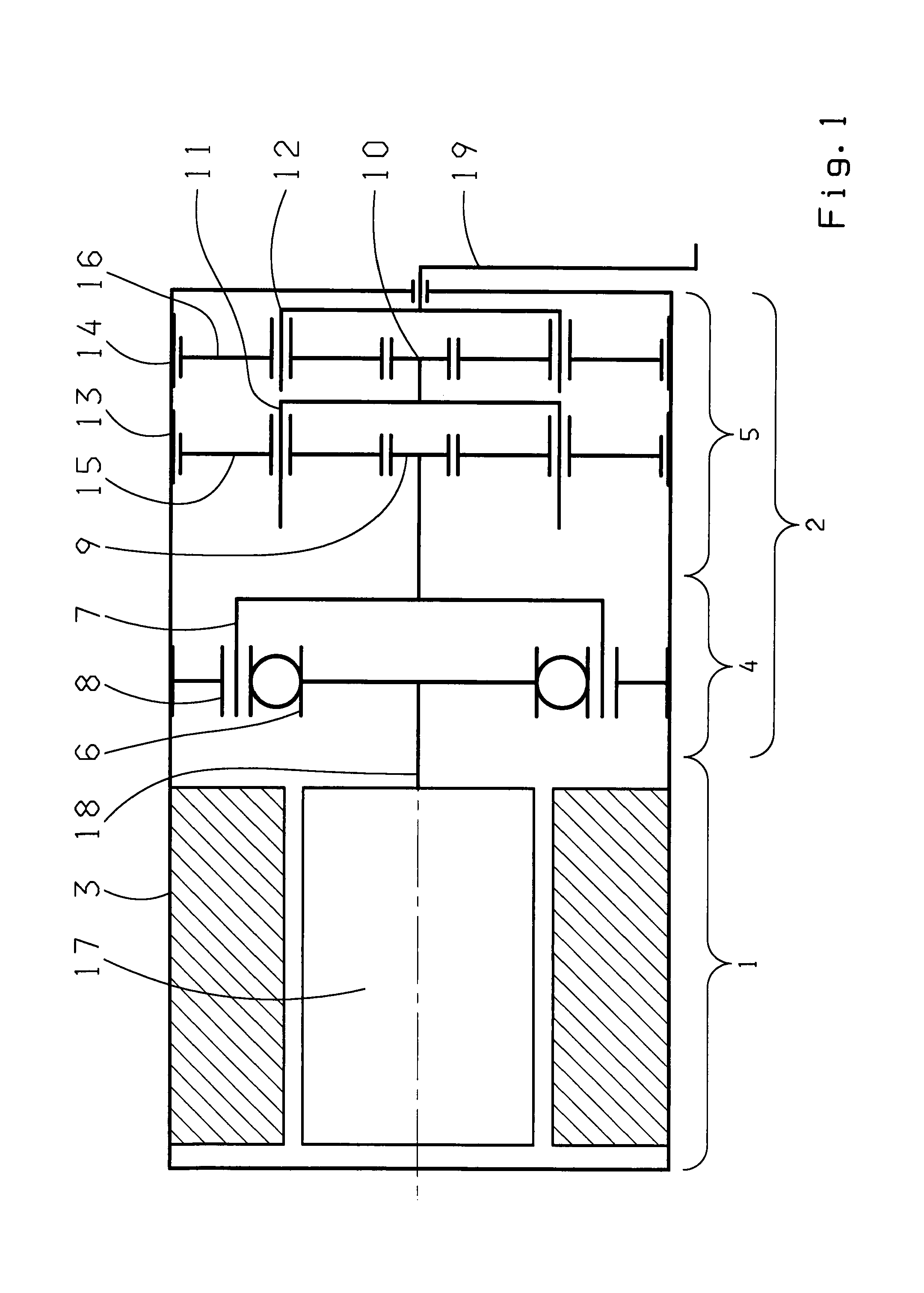
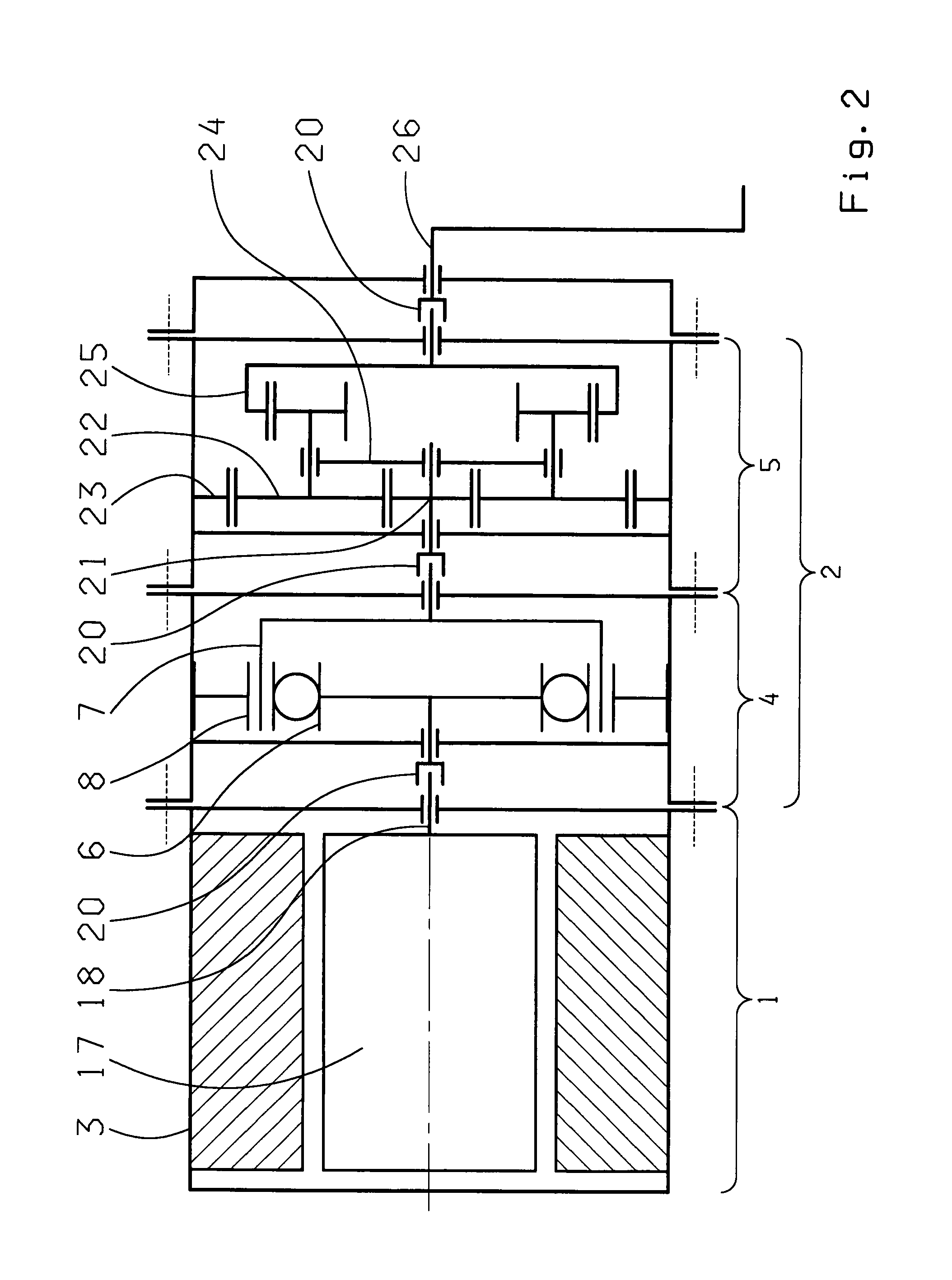
[0017]The actuator shown in FIG. 1 for generating rotational positioning movements comprises an electric motor 1 and a reduction gear 2 which are mounted in a common housing 3. The reduction gear 2 consists of two assemblies 4, 5, the first assembly 4 consisting of a well-known harmonic gear having a wave generator 6, an elastic wheel 7 and a rigid wheel 8, and the second assembly 5 consisting of a well-known two-step planetary gear having two sun gears 9, 10, two planet carriers 11, 12, two ring gears 13, 14 and at least two planetary gears 15, 16. For the generation of rotational positioning movement, the motor output shaft 18 attached to the rotor 17 of the electric motor 1 actuates the wave generator 6 of the harmonic gear, generating the rotation of the elastic wheel 7 against the rotational direction of the wave generator 6 owing to the difference in the number of teeth between the elastic wheel 7 and the rigid wheel 8. The elastic wheel 7 forms the output element of the harmo...


PUM


Abstract

The present invention relates to an actuator for generating a rotational positioning movement, wherein the actuator comprises an electric motor (1) and a reduction gear (2) which consists of two assemblies (4, 5). The first assembly (4) is formed by a gear of the harmonic, cycloid or wobble, type and the second assembly (5) by a gear of the single-step or multistep planetary or Wolfrom type, whereby both assemblies (4, 5) are so tuned to each other, that the reduction gear (2) is not self-locking.

Description

[0001]This application is a National Stage completion of PCT / EP2007 / 063112 filed Dec. 3, 2007, which claims priority from German patent application serial no. 10 2006 058 133.4 filed Dec. 9, 2006.FIELD OF THE INVENTION[0002]The present invention relates to an actuator for generating rotational positioning movement.BACKGROUND OF THE INVENTION[0003]Actuators are frequently used in vehicles for generating positioning movements which are controlled by the system or the driver. Actuators may, for example, adjust a vehicle seat, support the steering force or adjust the ride height of the chassis to the driving speed. The energy required for this purpose is normally provided in electric, hydraulic or pneumatic form, whereby electric actuators may be cost-effectively positioned in nearly any place in the vehicle because of the easy transfer of the electric energy from the energy source to the actuator. Moreover, nearly all types of vehicles have an electric energy source, like a generator o...

Claims


Application Information

Patent Timeline
Patent Type & Authority Applications(United States)
IPC IPC(8): F16H37/00F16H1/20F16H1/28B60G21/055B62D5/04B66D1/12
CPCB60G21/0555B60G2202/42B60G2204/62B60G2204/82B60G2204/8302F16H1/28Y10T74/19647F16H37/00F16H37/041F16H49/001F16H2001/2881H02K7/116F16H1/32
Inventor WOELLHAF, PAULDOERNER, ROLAND
Owner ZF FRIEDRICHSHAFEN AG
Learn More