
Electronic device and a thermal connector used therein

Inactive Publication Date: 2010-03-25
HITACHI LTD
View PDF8 Cites 10 Cited by
  • Summary
  • Abstract
  • Description
  • Claims
  • Application Information

AI Technical Summary

Benefits of technology

[0019]The invention has been thought of in view of the problems in the related art and has its object to provide a thermal connector, by which a heat release part and a heat absorbing part are made detachable and which connects between the heat release part and the heat absorbing part with a smaller heat resistance than a predetermined heat resistance, which complies with design specifications, and an electronic device, in which a cooling device using the thermal connector is not deteriorated in performance even when a CPU blade is repeatedly mounted to and dismounted from a server frame.
[0022]Therefore, a heat resistance between the heat release part of the first cooling means and the heat absorbing part of the second cooling means can be made smaller than a predetermined value, which complies with design specifications, volatile components contained in the heat conducting medium can be inhibited from diffusing into the atmosphere to be susceptible to deterioration, and mounting and dismounting between the heat release part of the first cooling means and the heat absorbing part of the second cooling means can be performed repeatedly.
[0024]Also, a sealing member is provided to maintain in airtight the medium reservoir and the clearance whereby it is possible to suppress deterioration of the heat conducting medium.
[0026]Therefore, it is possible to provide a thermal connector, by which first cooling means mounted to CPU loaded on a blade of an electronic device, which is easily detachable from a housing like a blade server, is made detachable from second cooling means fixed to the housing and heat from CPU can be transported to the second cooling means from the first cooling means, and an electronic device, which is high in performance and in reliability and uses the thermal connector.

Problems solved by technology

However, by virtue of CPUs being spectacularly increased in heat generation amount and blades being thinned, measures of mounting a heat sink to a CPU to perform air-cooling in a blade approaches a limit.
On the other hand, the cooling system involves a problem of realizing hot-swap.
However, this method involves a danger of liquid leakage since refrigerant liquid circulates through the coupler between the heat transport device in a blade and the heat transport device outside a blade.
However, a specific structure of the thermal connector is not disclosed.
Because of a system, in which the solid surfaces come into contact with each other to transfer heat therebetween, however, it is difficult in some cases to achieve a decrease in heat resistance due to influences of machining accuracy (surface roughness, waviness, etc. of tapered surfaces) of surfaces in contact with each other.
Because of a system, in which the heat pipe is inserted axially into the receiving portion, however, it is difficult to form a structure, in which the heat pipe and the receiving portion are brought into close contact with each other, so that a contact area being effective for heat transfer becomes small to make it difficult to achieve a decrease in heat resistance.
When a heat conducting medium such as grease, oil, or the like is used in an opened space over a long term, there is caused a problem that volatile components contained in the heat conducting medium diffuse in an outside air to lead to deterioration.
With the conventional technology disclosed in JP-A-8-116005, however, a semiconductor module cannot be exchanged unless a closed device is disassembled after the device is stopped and oil is removed, so that only a part of blades cannot be pulled out or inserted to be exchanged while the whole server remains in operation.
That is, hot-swap, which characteristic of a blade server, becomes difficult.
In summary, in an electronic device, such as a blade server, in need of hot-swap, it is problematic to make measures against deterioration of grease and hot-swap compatible with each other in case of using a thermal connector, in which a heat conducting medium such as grease is present.

Method used


Image

  • Electronic device and a thermal connector used therein
  • Electronic device and a thermal connector used therein
  • Electronic device and a thermal connector used therein

Examples


first embodiment

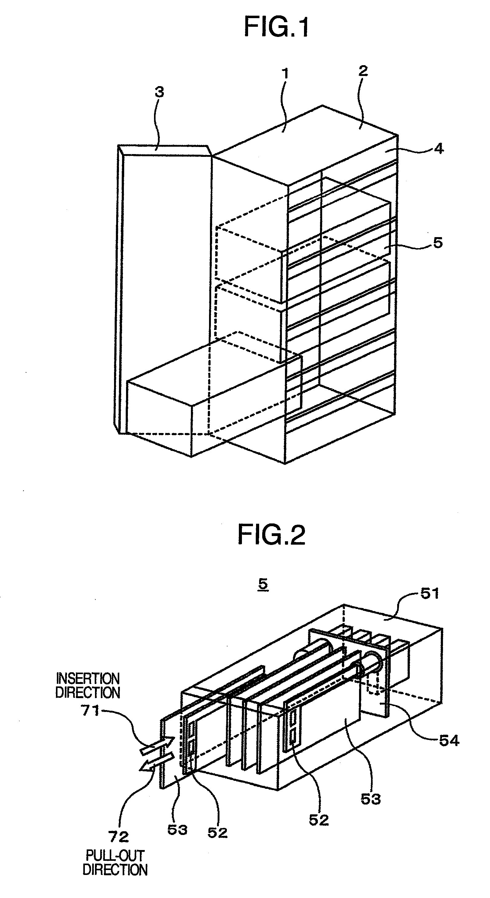
[0040]FIG. 1 is a conceptual, perspective view showing construction of an electronic device of rack mount system of the invention, in which a blade servers etc. are mounted. FIG. 1 shows, in perspective, a part of the electronic device for the sake of understanding. In addition, as shown in FIG. 1, a rack mount cabinet 1 includes a housing 2, a lid 3, and a plurality of shelves 4 formed to assume a shape based on particular standards such as IEC (International Electrical Commission) standards / EIA (The Electrical Industries Association) standards, or the like. Blade servers 5 having individual functions can be selectively mounted in a free arrangement on the plurality of shelves 4 whereby the system structure can have both flexibility and scalability.

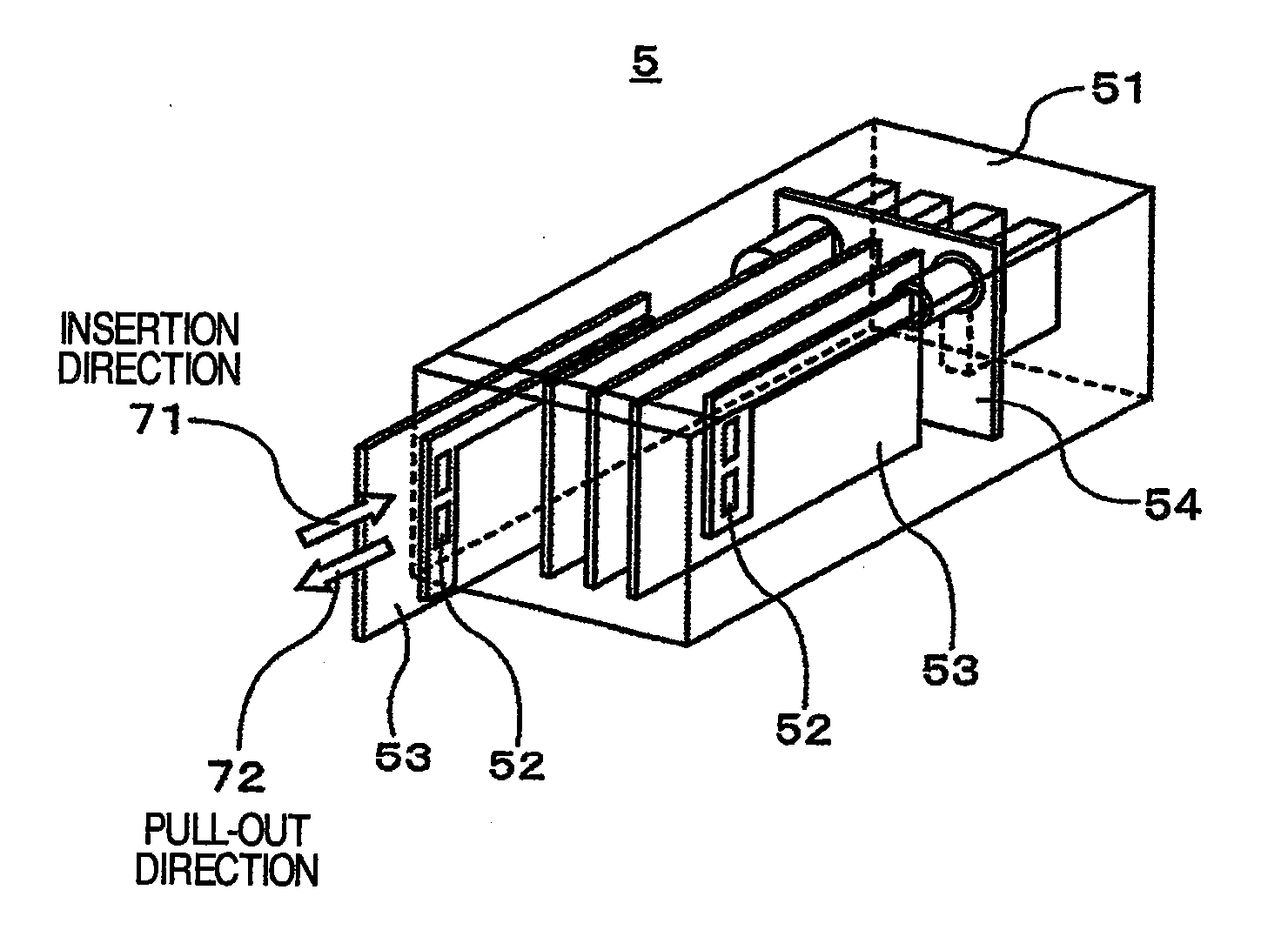
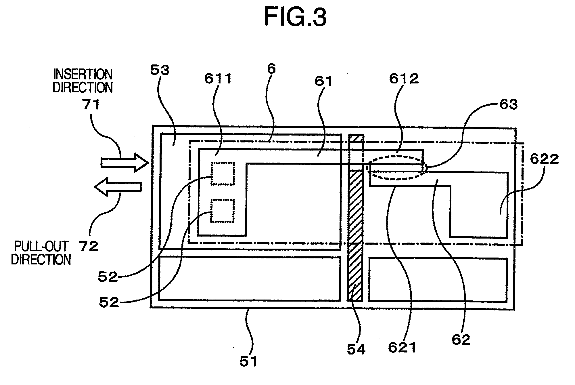
[0041]FIG. 2 is a perspective view showing an outline of structure of the blade server 5 in the invention. The blade server 5 includes, in a server frame 51, a plurality of CPU blades 53 on each of which a CPU 52 is mounted, a backplane ...

second embodiment

[0078]A connecting mechanism on the thermal connector in a second embodiment according to the invention will be described with reference to FIG. 10.

[0079]The second embodiment is the same as the first embodiment in the structures of first cooling means 61, second cooling means 62, and a thermal connector but different therefrom in the structure of a connecting mechanism, in which a bolt 6344 attached to a cap 634b is rotated by means of a tool from a back surface side of the server frame 51 shown in FIG. 2, that is, a right side in FIG. 2 whereby the cap 634b and a heat release part 612b of the first cooling means 61 are coupled together.

[0080]Before the CPU blade 53 is pulled out from the server frame 51, the bolt 6344 attached to the cap 634b is screwed in a female thread portion 614 of the heat release part 612b of the first cooling means 61 by means of a tool from a back surface side of the server frame 51, that is, a right side in FIG. 10 whereby the heat release part 612b of t...

third embodiment

[0084]The third embodiment has a feature in that a medium reservoir 6321b is provided in a position being independent of a socket 632c.

[0085]As shown in FIG. 11, the medium reservoir 6321b is provided in the position being independent of the socket 632c and communicated to the socket 632c through a medium inflow hole 623. The heat conducting medium 631 is pressurized in the medium reservoir 6321b whereby the heat conducting medium 631 is caused to flow into the clearance 636 from the medium inflow hole 623. A rod 637 serves to pressurize the heat conducting medium 631.

[0086]The rod 637 is mounted to the CPU blade 53 sown in FIG. 3 whereby it interlocks with the CPU blade 53 to be pushed and moved in a direction, in which the heat conducting medium 631 is pressurized, to pressurize the heat conducting medium 631. At this time, the rod 637 may be mounted to the CPU blade 53, shown in FIG. 3, through a compression spring (not shown).

[0087]Alternatively, the rod 637 may be pushed and m...


PUM


Abstract

An electronic device comprises: a housing; blades each of which is detachable from the housing and on each of which at least CPU and a memory are mounted; first cooling devices each of that takes out heat generated in the blade outside the blade, each of said first cooling device having a heat release part in the form of an elongate column to be fixed to the blade; second cooling devices fixed to the housing to discharge heat transported from the first cooling devices outside the housing, each of said second cooling devices having a heat absorbing part, which is capable of containing the heat release part of the first cooling device; medium reservoirs each of which is put in fluid communication with a clearance, which is formed between the heat release part and the heat absorbing part when the heat release part is inserted into the heat absorbing part; a heat conducting medium stored in each of the medium reservoirs; pressurizing devices for pressurizing the heat conducting medium to supply the heat conducting medium to the clearance, and a detachable connecting part formed between the heat release part and the heat absorbing part.

Description

BACKGROUND OF THE INVENTION[0001]The present invention relates to an electronic device typified by blade servers which have been going to prevail rapidly in recent years, and more particular, to a thermal connector suited to be used in such electronic device, and an electronic device using the same.[0002]Blade servers are offered in a state, in which blades having devices such as CPU (Central Processing Unit), a memory, a hard disk, etc. are loaded into a rack on which a power unit, a fan unit, a management module, etc. are mounted. In particular, the invention relates to a thermal connector between a heat pipe, through which heat of CPU is taken out from a blade, and a heat release device, from which heat taken out through the heat pipe is further discharged outside a rack.[0003]In blade servers which have been rapidly increased in demand in recent years, further improvements in information processing capability and space-saving have been demanded. The information processing capabi...

Claims


Application Information

Patent Timeline
IPC IPC(8): G06F1/20
CPCG06F1/185H05K7/20772G06F1/20
Inventor HAYASHI, TOMOONAKAJIMA, TADAKATSUKONDO, YOSHIHIROTOYODA, HIROYUKIIDEI, AKIOTSUBAKI, SHIGEYASU
Owner HITACHI LTD
Learn More