Cooling device and electronic equipment including cooling device

a cooling device and electronic equipment technology, applied in lighting and heating apparatus, electric apparatus casings/cabinets/drawers, instruments, etc., can solve the problems of large constraints on the mounting place, the size of the heat radiation fins of the cpu attached to the blade, and the difficulty of loading a high-performance cpu with a large amount of heat generation on the blade, so as to reduce the thermal resistance and improve the maximum heat transport amount performance.

Inactive Publication Date: 2010-03-25
HITACHI LTD
View PDF20 Cites 30 Cited by
  • Summary
  • Abstract
  • Description
  • Claims
  • Application Information

AI Technical Summary

Benefits of technology

[0016]In recent yeas, a product called a blade server has been widespread, which realizes reduction of the physical space by loading the elements necessary as a computer such as a CPU, a memory, and an HDD on one thin blade, housing a plurality of such blades in a casing called a chassis or the like, and communalizing a power supply, a cooling fan, and input and output of information such as a LAN in the chassis. One blade has the same function as one server, and by loading a plurality of the blades on a chassis, the blade server has the characteristic of high mounting density of servers as compared with the other server equipment having about the same volume as the chassis.

Problems solved by technology

However, in order to realize high density mounting which is one of its characteristics, the size of the heat radiation fins for the CPU attached to the blade, and the place for mounting them have large constraints.
Therefore, it becomes difficult to load a high performance CPU with a large heat generation amount on a blade.

Method used


Image

  • Cooling device and electronic equipment including cooling device
  • Cooling device and electronic equipment including cooling device
  • Cooling device and electronic equipment including cooling device

Examples


embodiment 1

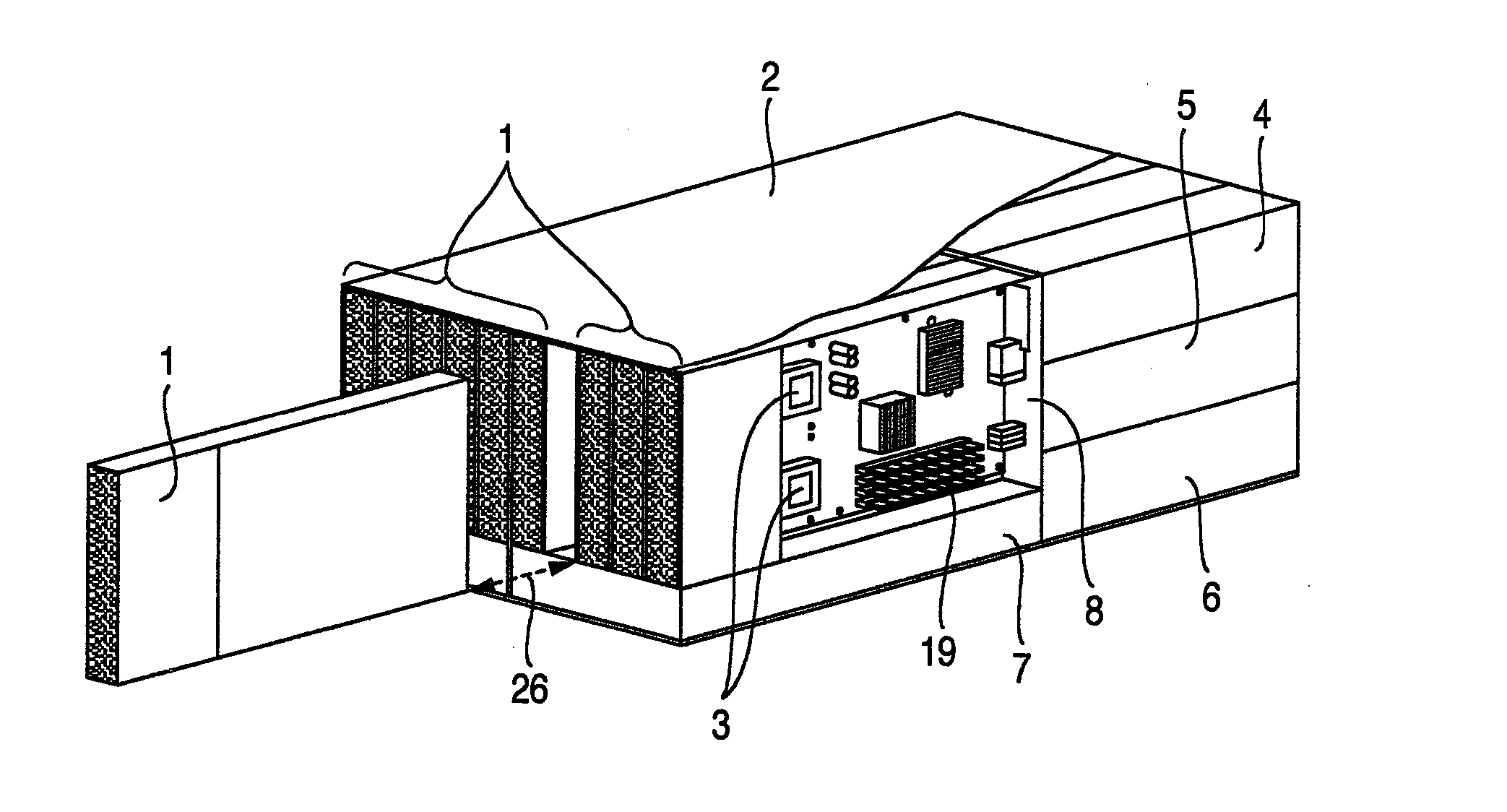
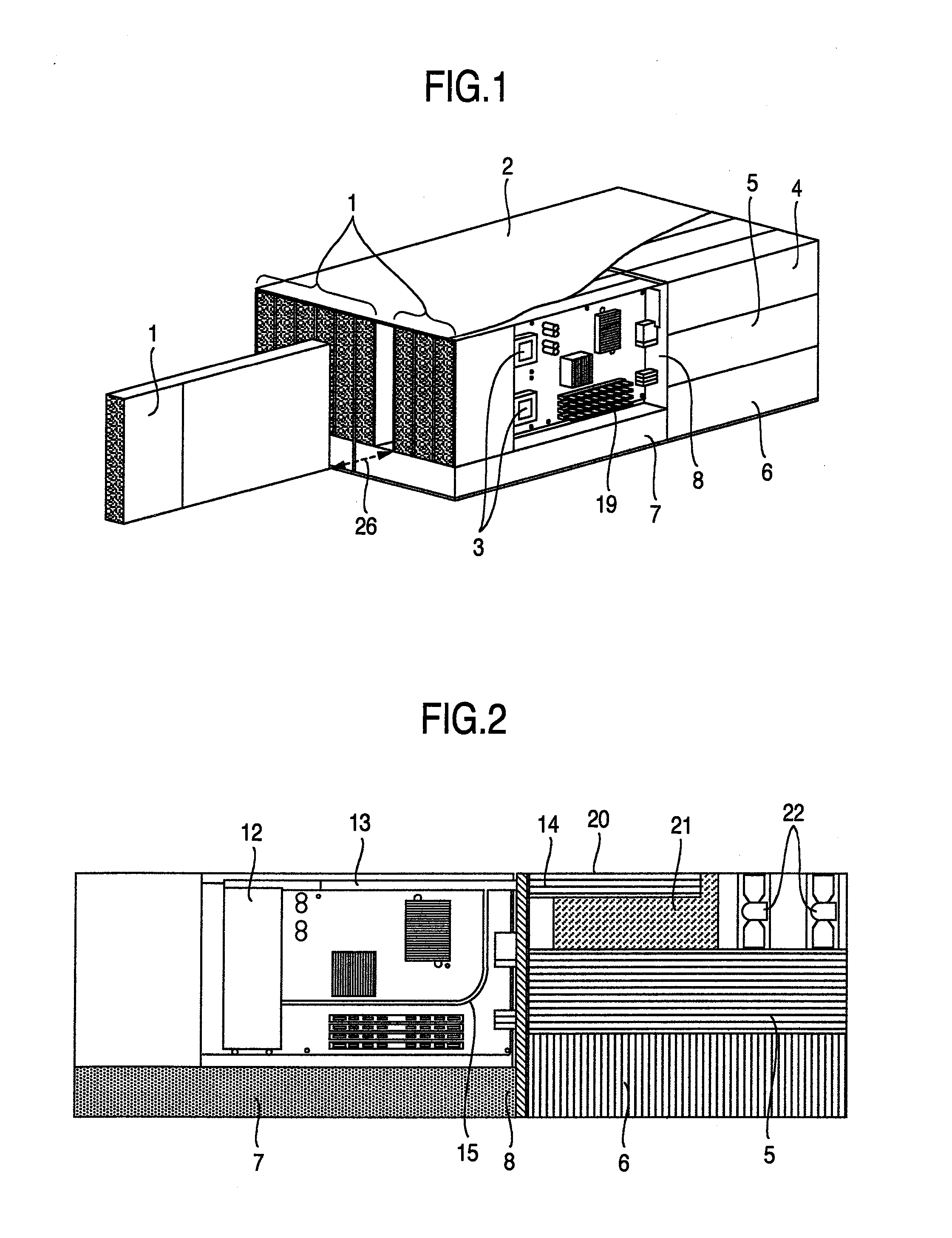
[0063]FIG. 1 is a perspective view for explaining a schematic configuration of an ordinary blade server.

[0064]In FIG. 1, the blade server is configured by a server device which is called a thin blade 1 constituted of necessary elements as a computer such as a CPU 3, a memory 19 and an HDD, and what is called a chassis 2 which is mounted with a plurality of blades and constituted of devices and the like which perform power supply to the blades, and perform input and output of information to and from an external part, such as a LAN. Though the details are not illustrated, in the chassis 2, a fan unit 4 loaded with a fan for cooling the entire blade server, an I / O unit 5 to be an interface for performing input and output of information to and from the external part such as a LAN, a power supply unit 6 which performs power supply, a system unit 7 which performs management of the blade and the like are electrically connected by a back plane 8. By adopting these configurations, the blade ...

embodiment 2

[0095]FIG. 7 is a partial perspective view of a vapor condensing pipe including another embodiment.

[0096]In FIG. 7, the flow of vapor and the flow of condensate liquid flowing in the wick 9 are opposed to each other in the structure of embodiment 1. The condensate liquid returns to the working fluid chamber 35 (shown in FIG. 3) by the capillary force of the wick 9 even under the influence of the flow of vapor, but in order to increase the maximum heat transport amount more, it is desirable to reduce the influence as much as possible. Thus, in the present embodiment, in the vapor condensing pipe 14 shown in embodiment 1, a partition plate 24 having a partition plate opening 25 is provided on the top surface of the wick 9 of the internal structure of the vapor condensing pipe 14, so that the flow of the vapor does not influence the flow of the condensate liquid in the wick 9.

[0097]In the structure of the present embodiment, the liquid which is condensed in the fins flows to the wick 9...

embodiment 3

[0099]FIG. 8 is a sectional view of a heat pipe including still another embodiment.

[0100]In FIG. 8, in the structure of the vapor condensing pipe 14 shown in embodiment 1, the flow of vapor and the flow of the condensate liquid flowing in the wick 9 are opposed to each other. Thus, an inner vapor pipe 28 is provided inside the vapor condensing pipe 14 via a spacer 34 so as to form the structure in which the vapor from the vapor pipe 13 passes through the inner vapor pipe 28 and is released to the end of the vapor condensing pipe 14. Thereby, the vapor released from the inner vapor pipe 28 flows to the condensate liquid return pipe 15 from the tip end of the heat pipe, and the flow of the vapor is parallel with the flow of the condensate liquid flowing in the wick 9. Therefore, the flow of the condensate liquid flowing in the wick 9 is promoted by the flow of the vapor, and the draining performance to the condensate liquid return pipe 15 is enhanced, which results in increase in the ...


PUM


Abstract

A blade server including a cooling structure to be loaded with a CPU of high performance is provided. In order to enhance draining performance of a condensed working fluid which stays between fins, a vapor condensing pipe is used, in which grooves are formed in a direction substantially parallel direction with a pipe axis direction on the above described pipe inner surface, a section of a row of the above described fins is exposed on a side surface of the above described groove, the above described groove is disposed at a lower side in the vertical direction from the center line in the pipe axis direction of the vapor condensing pipe when the above described groove is installed in the above described vapor condensing pipe, and a wick with a wire space smaller than the fin space of the above described fin row is filled inside the above described groove.

Description

BACKGROUND OF THE INVENTION[0001]The present invention relates to a cooling device and electric equipment including the cooling device, such as blade servers.[0002]In recent years, in blade servers, for which demand has been rapidly growing, further increase in information processing capability and space saving have been required. The information processing capability has been drastically enhanced year after year with enhancement in the performance of a single CPU. Further, by increasing the number of CPUs loaded on one blade, enhancement in the information processing capability per one blade is designed. Further, by reducing the thickness of a blade, the number of blades which can be loaded on one rack is increased.[0003]By increase in heat generation amount following enhancement in performance of a CPU, and reduction in thickness of a blade, the heat generation density of the blade server is drastically increased. Therefore, enhancement in cooling efficiency is desired. Further, t...

Claims


Application Information

Patent Timeline
Patent Type & Authority Applications(United States)
IPC IPC(8): H05K7/20F28F13/00
CPCF28D15/043F28D15/046H05K7/20809H01L2924/0002H01L2924/00
Inventor TOYODA, HIROYUKIIDEI, AKIOTSUBAKI, SHIGEYASUNAKAJIMA, TADAKATSUKONDO, YOSHIHIROHAYASHI, TOMOO
Owner HITACHI LTD
Why Eureka
Try Eureka