Deformable thermal pads for optical fibers

Inactive Publication Date: 2010-03-25
ELECTRO SCI IND INC
View PDF11 Cites 23 Cited by
  • Summary
  • Abstract
  • Description
  • Claims
  • Application Information

AI Technical Summary

Benefits of technology

[0011]Numerous benefits are achieved using the present invention over conventional techniques. According to the embodiments of the invention, a fiber coil may be embedded in at least one or more deformable thermal pads, which helped with better thermal conduction. Additionally, external cooling devices such as thermoelectric coolers (TECs), fluid pipes carrying coolant like water, blowing fans further help maintain constant temperatures for the fiber coil with high power applications. For high p

Problems solved by technology

The coiling of fibers has been a challenge for many applications, as coiling may perturb modal properties of the fibers, resulting in undesirable modes being favored over a more preferred fundamental mode.
In particular, if the fiber in the coil is heated as a result of the high power

Method used


Image

  • Deformable thermal pads for optical fibers
  • Deformable thermal pads for optical fibers
  • Deformable thermal pads for optical fibers

Examples


Embodiment Construction

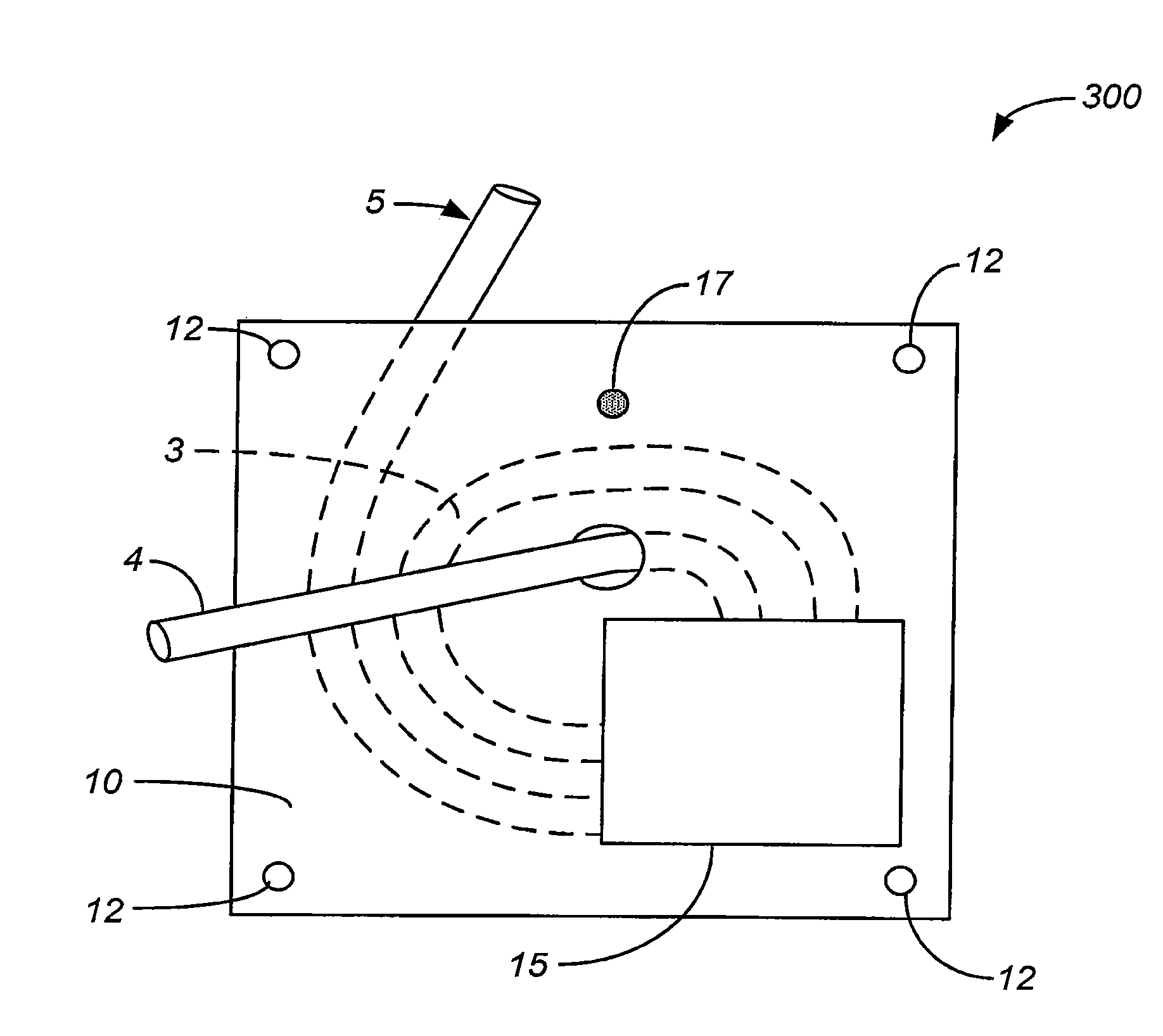
[0024]A typical approach used for fiber coiling is to coil the optical fiber around a metallic mandrel for purposes of heat extraction. In one of the common designs, a fiber is wrapped around an oval shaped mandrel to have at least 5 loops of the fiber. The fiber is preferably fit inside a laser enclosure of a small size in comparison with the length of the fiber since miniaturization is one of the key features of a fiber laser. The fiber may be tightly wrapped around the mandrel to enhance heat conduction and the adjacent fibers often touch each other. A metal sleeve is usually attached to the mandrel on the outside edge of the fiber coil. The metal containing holder may not provide a uniform contact between the fiber and the metal containing holder at all the locations.

[0025]Furthermore, the fiber and the mandrel may expand differentially as laser power generates heat. This heat may cause undesirable thermal stress on the fiber. Moreover, such induced stress and temperature change...


PUM

PropertyMeasurementUnit
Temperatureaaaaaaaaaa
Lengthaaaaaaaaaa
Shapeaaaaaaaaaa

Abstract

A system for fiber optic packaging includes a first substrate and a first deformable pad coupled to the first substrate. The first deformable pad is characterized by a thermal conductivity greater than 1 W/mK. The system also includes a fiber coil having at least a portion embedded in the first deformable pad to provide physical contact between the at least a portion of the fiber coil and the first deformable pad. The system further includes a second substrate coupled to the fiber coil and at least a portion of the first deformable pad.

Description

BACKGROUND OF THE INVENTION[0001]The present invention relates generally to packaging of optical fibers. More particularly, an embodiment related to a method and system for packaging of an optical fiber coil in a compact form that provides efficient heat sinking, but with minimal stress on the optical fiber. The present invention is not limited to this particular application, but has a wider field of use.[0002]High power fiber lasers, such as high power pulsed fiber lasers, typically employ a fiber design referred to as Large Mode Area (LMA) fiber. These fibers are inherently multi-mode, and thus generally produce multi-mode outputs from fiber lasers and / or fiber amplifiers. High power fibers may be doped fibers, for example, doped with Ytterbium at 6×1026 ions / m3. Coiling the fibers is generally used in many fiber system in order to package the fiber in a convenient, small size. The coiling of fibers has been a challenge for many applications, as coiling may perturb modal propertie...

Claims


Application Information

Patent Timeline
IPC IPC(8): G02B6/00B21D53/02
CPCG02B6/4457Y10T29/4935H01S3/042H01S3/06704
Inventor PANARELLO, TULLIOBLANCHET, MARCCAPLETTE, STEPHANELAMOTHE, GHISLAIN
Owner ELECTRO SCI IND INC
Why Eureka
Try Eureka