Fluid Disinfection Unit For Patient Temperature Control System

a technology of patient temperature control and fluid disinfection unit, which is applied in disinfection, contraceptive devices, treatment water, etc., can solve the problems of contamination of medical patient temperature therapy, hard data has not been available to demonstrate just how serious this problem has become, and the infection acquired during hospital stay is a major health care issue, so as to reduce the adverse effects, reduce the time and labor, and prevent the effect of adverse effects

Active Publication Date: 2010-03-25
GENTHERM MEDICAL LLC
View PDF37 Cites 27 Cited by
  • Summary
  • Abstract
  • Description
  • Claims
  • Application Information

AI Technical Summary

Benefits of technology

[0010]The present invention seeks to address these problems in a practical and straightforward manner. More particularly, the present invention incorporates a UV light source directly into upper and lower chambers of a reservoir that contains replenishing and circulating fluid that is circulating to a patient warming/cooling device, such as a blanket. By simultaneously directing UV light into both chambers of the reservoir, during operation, this...

Problems solved by technology

It has long been suspected that infections acquired during a hospital stay are a major health care issue.
Until recently hard data has not been available to demonstrate just how serious this problem has become.
One historical difficulty with medical patient temperature therapy is contamination.
This issue exists for water systems as well as convective air systems, i.e. systems with closed loop fluid flow.
Nonetheless, poor maintenance practices can negate the overall effectiveness of these filters.
Contaminates can also enter the hose between uses.
Water based systems also have comparable challenges for staying safely clean.
When a water based device is cleaned, it is not practical to expect that every part of the surface area that can harbor algae or bacteria will be properly exposed to disinfectants to sanitize the system.
This is especially true when fundamental mistakes are made duri...

Method used


Image

  • Fluid Disinfection Unit For Patient Temperature Control System
  • Fluid Disinfection Unit For Patient Temperature Control System
  • Fluid Disinfection Unit For Patient Temperature Control System

Examples


Embodiment Construction

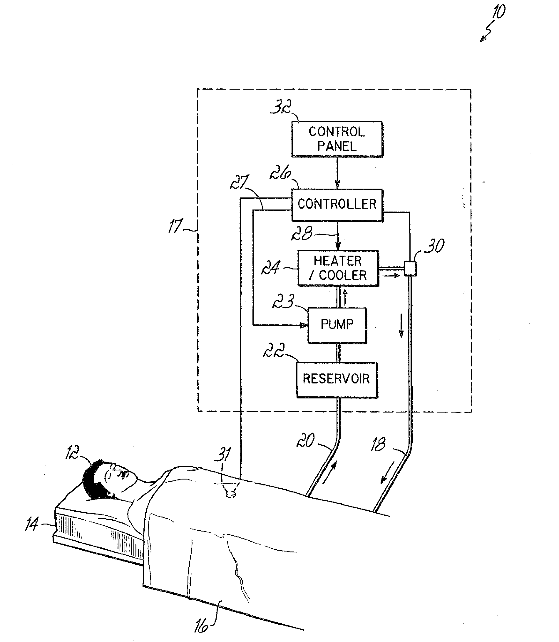
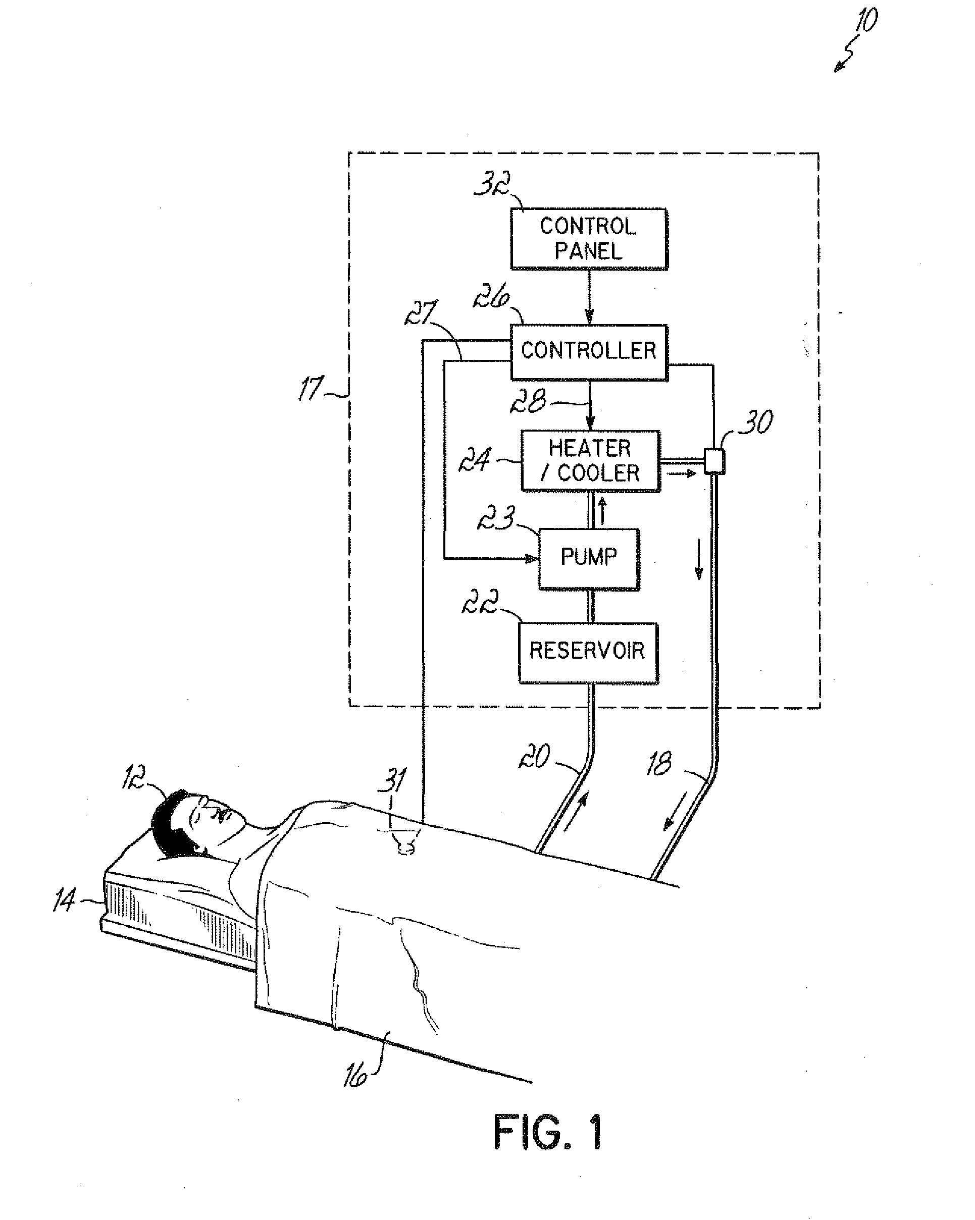
[0022]FIG. 1 shows a schematic layout of a patient temperature control system 10 of the type applicable to this invention. This layout is meant to supply the proper background and context for explaining the details of the present invention. It is not meant to be limiting in scope. More particularly, FIG. 1 shows a patient 12 supported on a table 14, with a warming / cooling device, in this case a blanket 16, substantially covering the patient 12. Other types of devices could be used to transfer heating or cooling to the patient 12. Water flow lines interconnect the blanket 16 with a housing, shown by a dash line 17. More particularly, FIG. 1 shows an inflow conduit line 18 which routes circulating fluid, preferably water, to the blanket 16, and an outflow line 20 which routes the circulating water back to the housing 17.

[0023]Within housing 17, water from the outflow line 20 flows to a reservoir 22. From the tank, or reservoir 22, the circulating water flows to a pump 23, then through...


PUM


Abstract

A fluid disinfection unit [40] is incorporated into a patient warming/cooling system [10], to reduce the risk of bacteria buildup in the warming/cooling fluid, which is typically water. More particularly, a mobile housing [17] contains the operable components for circulating warming/cooling fluid to a patient [12], including a pump [23], a heating/cooling source [24], a reservoir [22], a controller [26] and a control panel [32] to assist a user in operating the components. The reservoir [22] has upper [22a] and lower [22b] sections, for replenishing water and circulating water, respectively. A UV source [40] is mounted so as to extend through both reservoir sections [22a, 22b], to simultaneously emit UV light into both sections during circulation of the warming/cooling fluid, thereby to disinfect the water contained therein. The UV source [40] includes a bulb [42] protected within a transparent cover [44] that is completely transparent, and has been treated so as to be shatterproof. A sensor [70] mounted to the housing [17] detects the UV emission level within the reservoir [22], and generates a signal to indicate the on/off status of the UV bulb [42], and/or the magnitude of the UV light within the reservoir [22].

Description

RELATED APPLICATION[0001]This application claims priority to prior U.S. Provisional Patent Application No. 60 / 869,739, bearing the same title, which is expressly incorporated by reference herein, in its entirety.FIELD OF THE INVENTION[0002]This invention relates to patient temperature control, and more particularly, to a patient temperature control system and method that reduces susceptibility to contamination which can cause patient infection.BACKGROUND OF THE INVENTION[0003]It has long been suspected that infections acquired during a hospital stay are a major health care issue. Until recently hard data has not been available to demonstrate just how serious this problem has become. Pennsylvania was the first state to collect data tracking numbers and the results of hospital-acquired infections. The results are staggering.[0004]For instance, applicants understand that this collected data shows that in 2004, at least 12,000 patients in Pennsylvania developed infections while in a hos...

Claims


Application Information

Patent Timeline
IPC IPC(8): A61F7/00
CPCC02F2103/026C02F2201/008C02F2201/326C02F2303/04C02F1/32A61F2007/0054A61F2007/126A61L2/10A61L2/24A61F7/0085
Inventor BERAN, ANTHONY V.BATTA, JEROME B.ARONHALT, JACQUELINE C
Owner GENTHERM MEDICAL LLC
Why Eureka
Try Eureka