Near-to-eye scanning display with exit-pupil expansion

a scanning display and eye-to-eye technology, applied in the field of display devices, can solve the problems of constant power consumption regardless of the information content of the display, large size of the imaging optics and the related illumination system, etc., and achieve the effect of minimizing light loss and minimizing light loss

Inactive Publication Date: 2010-04-01
NOKIA CORP
View PDF7 Cites 220 Cited by
  • Summary
  • Abstract
  • Description
  • Claims
  • Application Information

AI Technical Summary

Benefits of technology

[0010]According further to the first aspect of the invention, the apparatus may further comprise: a quarter-wavelength plate placed between the exit-pupil expander and the scanning mirror, configured to minimize light losses of the one or more optical beams coupled to the exit-pupil expander for providing the one or more scanning near-to eye image displays with the expanded exit ...

Problems solved by technology

This approach requires somewhat large size of the imaging optics and the related illumination system.
Moreover, use of LCD requires always-on illumination ...

Method used


Image

  • Near-to-eye scanning display with exit-pupil expansion
  • Near-to-eye scanning display with exit-pupil expansion
  • Near-to-eye scanning display with exit-pupil expansion

Examples


Embodiment Construction

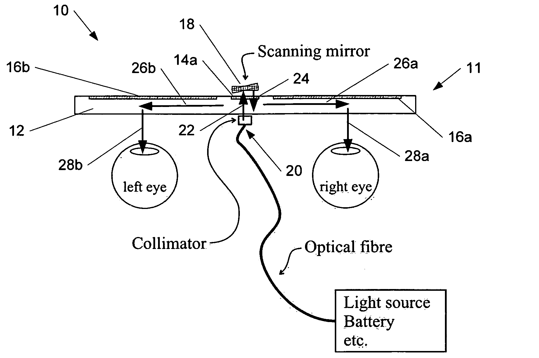
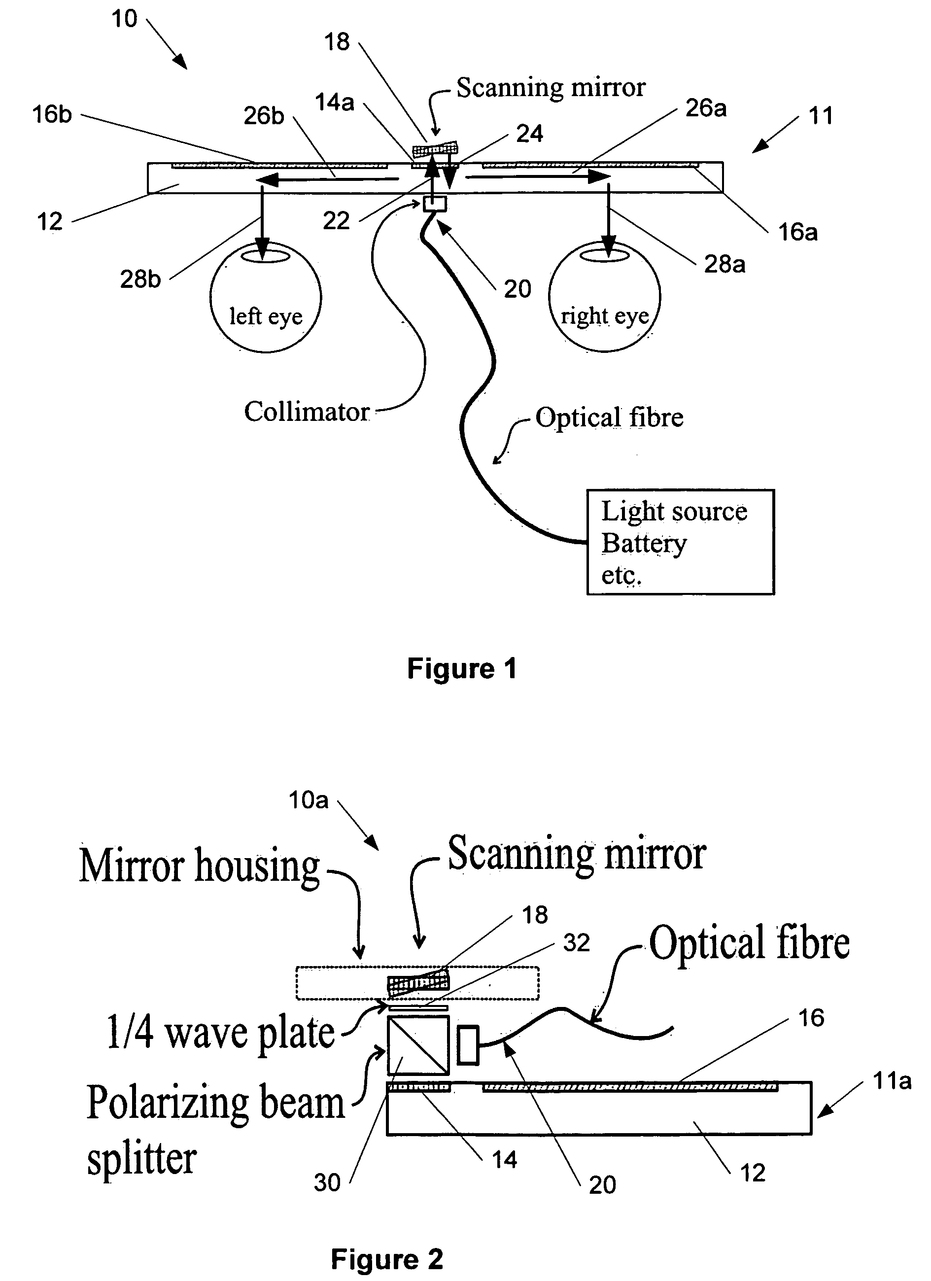
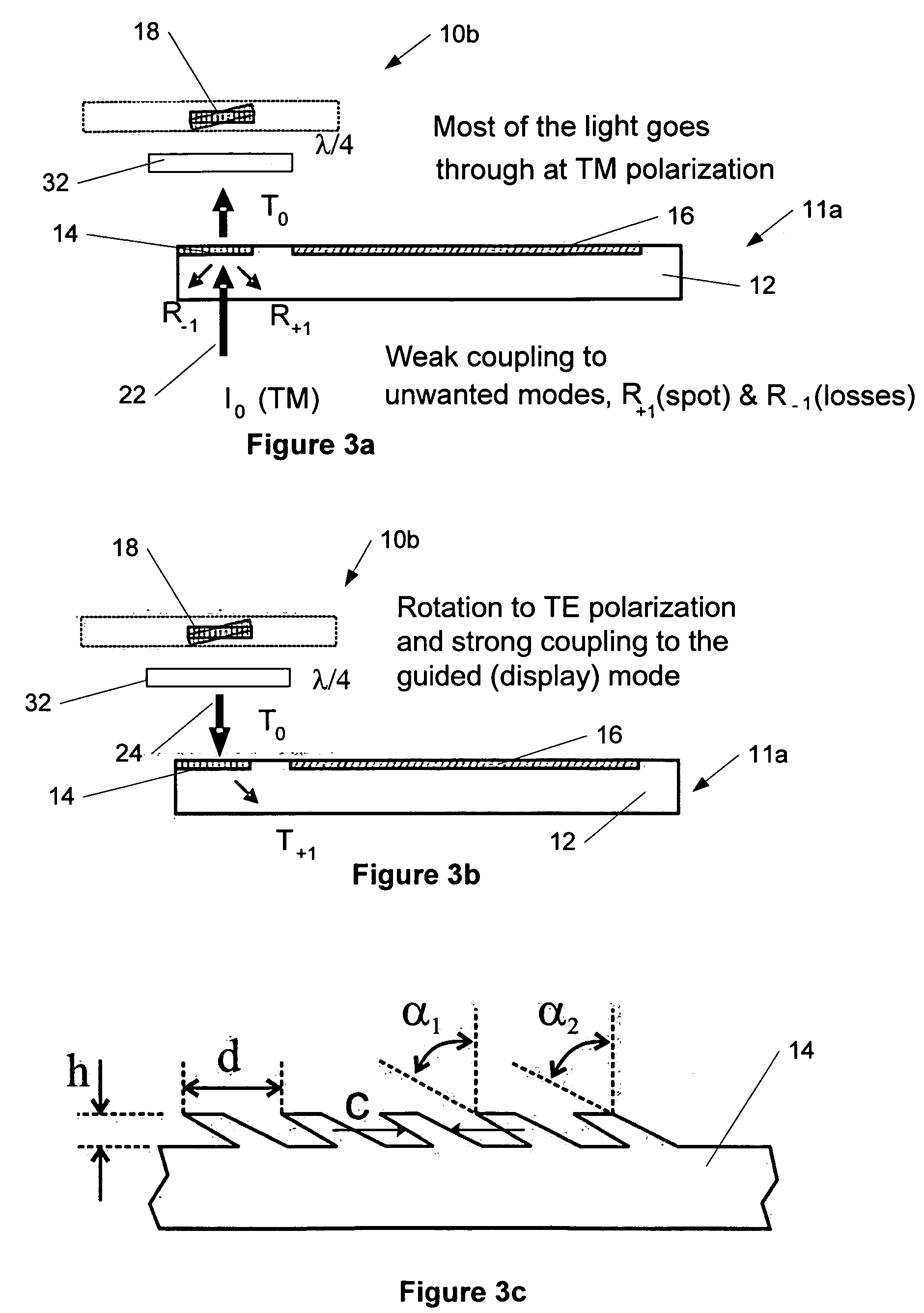
[0030]A new method and apparatus are presented for near-to-eye (e.g., retinal) displaying with exit-pupil expansion using a scanning component (e.g., a scanning mirror) and an exit-pupil expander, e.g., diffractive exit-pupil expander, for providing a retinal-scanning display with a large exit pupil. The embodiments of the present invention can be applied to a broad optical spectral range of optical beams but most importantly to a visible part of the optical spectrum where the optical beams are called light beams.

[0031]At a conceptual level, various embodiments of the present invention may combine the idea of the retinal scanning display with the diffractive exit-pupil expander to form a scanning-beam display with a large exit-pupil. At a technical level, the embodiments of the invention may provide a compact solution for implementation, e.g., of a MOEMS (micro (opto) electromechanical systems)—mirror-based scanning-beam display engine for the EPE plate.

[0032]According to various em...


PUM


Abstract

The specification and drawings present a new apparatus and method for near-to-eye (e.g., retinal) displaying with exit-pupil expansion using a scanning component (e.g., a scanning mirror) and an exit-pupil expander (e.g., diffractive exit-pupil expander) for providing a retinal scanning display with a large exit pupil.

Description

TECHNICAL FIELD [0001]The present invention relates generally to display devices and, more specifically, to near-to-eye-display (NED) technology for providing a retinal scanning display with a large exit pupil.BACKGROUND ART [0002]Three key features for all portable electric consumer products are low weight, small size and long operation time. The requirement of low weight and small size are particularly important for any device to be used as an eye wear, such as a near-to-eye display (NED). Moreover, the requirement of low power consumption is paramount to any multimedia device in the mobile context.[0003]The source image of a NED is generated by using two main techniques: active dot matrix (e.g. liquid crystal display panel), or a scanning-beam light source (c.f., cathode-ray tube, CRT). The source image is relayed to the viewer's eye(s) using an optical setup that allows the viewer to perceive the source image as a virtual display.[0004]The source image may be formed by scanning ...

Claims


Application Information

Patent Timeline
IPC IPC(8): G02B5/18
CPCG02B6/0016G02B6/0038G02B27/0081G02B7/12G02B26/105G02B6/0056G02B5/18G02B5/30G02B2027/012G02B27/0172
Inventor SAARIKKO, PASIAYRAS, PEKKA
Owner NOKIA CORP
Why Eureka
Try Eureka