Insert for forming an end connection in a uni-axial composite material

a composite material and insert technology, applied in the manufacture of final products, machines/engines, other domestic articles, etc., can solve the problems of flexural mismatch, material contribution to the overall mass, and hence cost, of the blade, and the cost of using more expensive materials, such as carbon fibre composite as required for larger blades, to achieve the effect of convenient reusability of the inser

Active Publication Date: 2010-04-08
BLADE DYNAMICS LTD
View PDF6 Cites 39 Cited by
  • Summary
  • Abstract
  • Description
  • Claims
  • Application Information

AI Technical Summary

Benefits of technology

[0035]The method preferably further comprises positioning a helical th...

Problems solved by technology

The uni-axial orientation of fibres in the root structure presents a problem for the formation of the female part of the hub connection.
Although the use of metallic inserts solves the problem of cutting female threads directly into the uni-axial “end grain” of the root structure, they have their own problems.
For example, structural problems can be caused by the thermal mismatch between the metallic inserts and the surrounding composite material, which have different ther...

Method used


Image

  • Insert for forming an end connection in a uni-axial composite material
  • Insert for forming an end connection in a uni-axial composite material
  • Insert for forming an end connection in a uni-axial composite material

Examples


Embodiment Construction

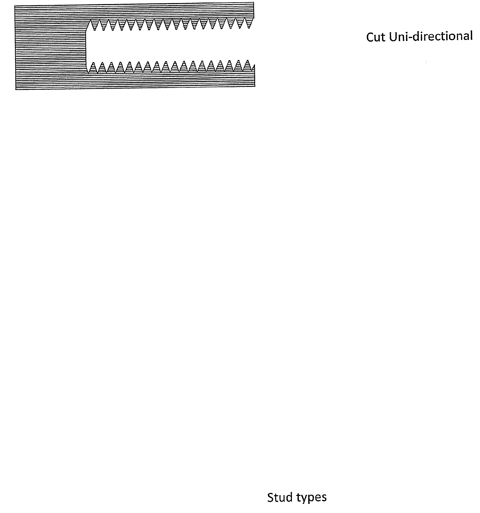
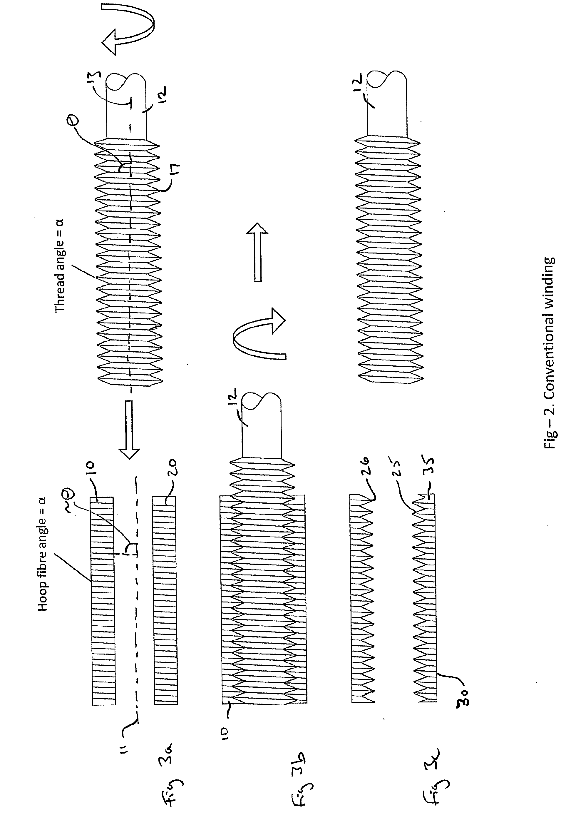
[0052]For clarity, the winding angle of the fibres 20 is the acute angle that the fibres 20 make with the major axis 11 of the tube 10 when the tube 10 is viewed from the side (FIG. 3a). Similarly, the thread angle of the thread cutting tool 12 is the acute angle that the threads 17 make with the major axis 13 of the thread cutting tool 12 when the thread cutting tool is viewed from the side (FIG. 3a). For the purposes of clarity in the Figures, only fibres 20 having a winding angle of approximately ±θ are illustrated in FIG. 3a. However, it will be understood that the tube 10 comprises fibres 20 having a winding angle of approximately ±θ.

[0053]In one example, the tube 10 may comprise standard e-glass and epoxy resin. However, any other suitable fibre composite material may be used such as e-glass and polyester or vinylester resin or carbon or aramid fibres.

[0054]FIG. 3b shows the filament wound fibre composite tube 10 during a thread tapping process. During the thread tapping proce...


PUM

PropertyMeasurementUnit
Fractionaaaaaaaaaa
Angleaaaaaaaaaa

Abstract

An insert for forming an end connection in a uni-axial composite material, and an end connection comprising at least one insert, is disclosed. The insert comprises a sleeve which comprises a plurality of fibres having a multi-axial arrangement. At least a portion of the interior surface of the sleeve comprises a thread formation. A method of forming an end connection in a uni-axial composite material is also disclosed. The method comprises providing a sleeve comprising a plurality of fibres having a multi-axial arrangement and providing a thread formation on at least a portion of the interior surface of the sleeve. The sleeve is positioned and secured within the uni-axial composite material.

Description

CROSS-REFERENCE TO RELATED APPLICATIONS[0001]This application claims benefit of British patent application number 0818467.3, filed Oct. 8, 2008, which is herein incorporated by reference.BACKGROUND OF THE INVENTION[0002]1. Field of the Invention[0003]The present invention relates to an insert for forming a high load carrying end connection in a uni-axial composite material. The present invention also relates to a method of forming an end connection in a uni-axial composite material using the insert. The present invention is exemplified by an insert for a root end of a wind turbine blade. However, the insert is also suitable for use in other applications and with other materials.[0004]2. Description of the Related Art[0005]In large horizontal axis wind turbines the wind turbine blades are connected to the rotor hub by a number of bolt attachment points. The hub end of the wind turbine blades (the root) is cylindrical in section and typically has a diameter of 1500 mm to 3000 mm. Appr...

Claims


Application Information

Patent Timeline
IPC IPC(8): B29C53/60B29D23/00F16B1/00
CPCB29C53/305Y10T156/1064B29C70/222B29C70/48B29C70/545B29C70/86B29D1/005B29D99/0025B29L2031/08F03D1/0658F05B2280/6003F05B2280/6013F05C2253/04F05C2253/16Y02E10/721B29C70/16Y02E10/72Y02P70/50
Inventor HAYDEN, PAUL TREVORWHILEY, DAVID ANTHONYBROOME, PETER ANTHONY
Owner BLADE DYNAMICS LTD
Why Eureka
Try Eureka