Bidirectional optical transceiver

a transceiver and optical transceiver technology, applied in the direction of optical elements, instruments, semiconductor lasers, etc., can solve the problems of difficult high-speed modulation exceeding 10 gbps, and achieve the effect of preventing thermal, electrical or optical crosstalk

Inactive Publication Date: 2010-04-08
ELECTRONICS & TELECOMM RES INST
View PDF9 Cites 22 Cited by
  • Summary
  • Abstract
  • Description
  • Claims
  • Application Information

AI Technical Summary

Benefits of technology

[0014]The following description relates to a bidirectional optical transceiver with a multi-layer structure which can prevent thermal, electrical or optical crosstalk.

Problems solved by technology

Accordingly, current leakage, electrical crosstalk and so on between peripheral transmission lines and electronic circuits occur, which makes high-speed modulation exceeding 10 Gbps difficult.
However, the conventional TO-can type bidirectional optical transceiver has a cylindrical structure in which a housing including a laser diode therein cannot efficiently transfer internally generated heat to an external heat sink.

Method used


Image

  • Bidirectional optical transceiver
  • Bidirectional optical transceiver
  • Bidirectional optical transceiver

Examples


Embodiment Construction

[0031]The detailed description is provided to assist the reader in gaining a comprehensive understanding of the methods, apparatuses and / or systems described herein. Various changes, modifications, and equivalents of the systems, apparatuses, and / or methods described herein will likely suggest themselves to those of ordinary skill in the art. Also, descriptions of well-known functions and constructions are omitted to increase clarity and conciseness.

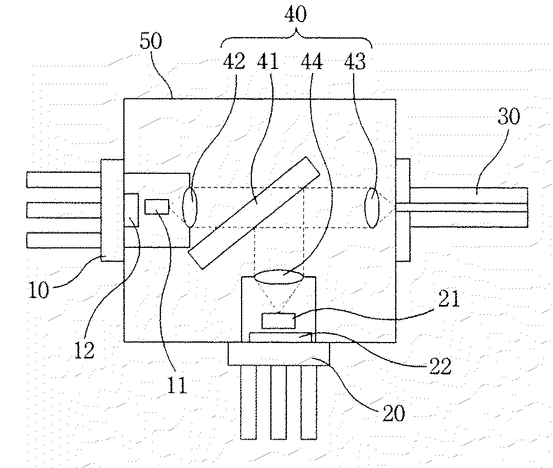
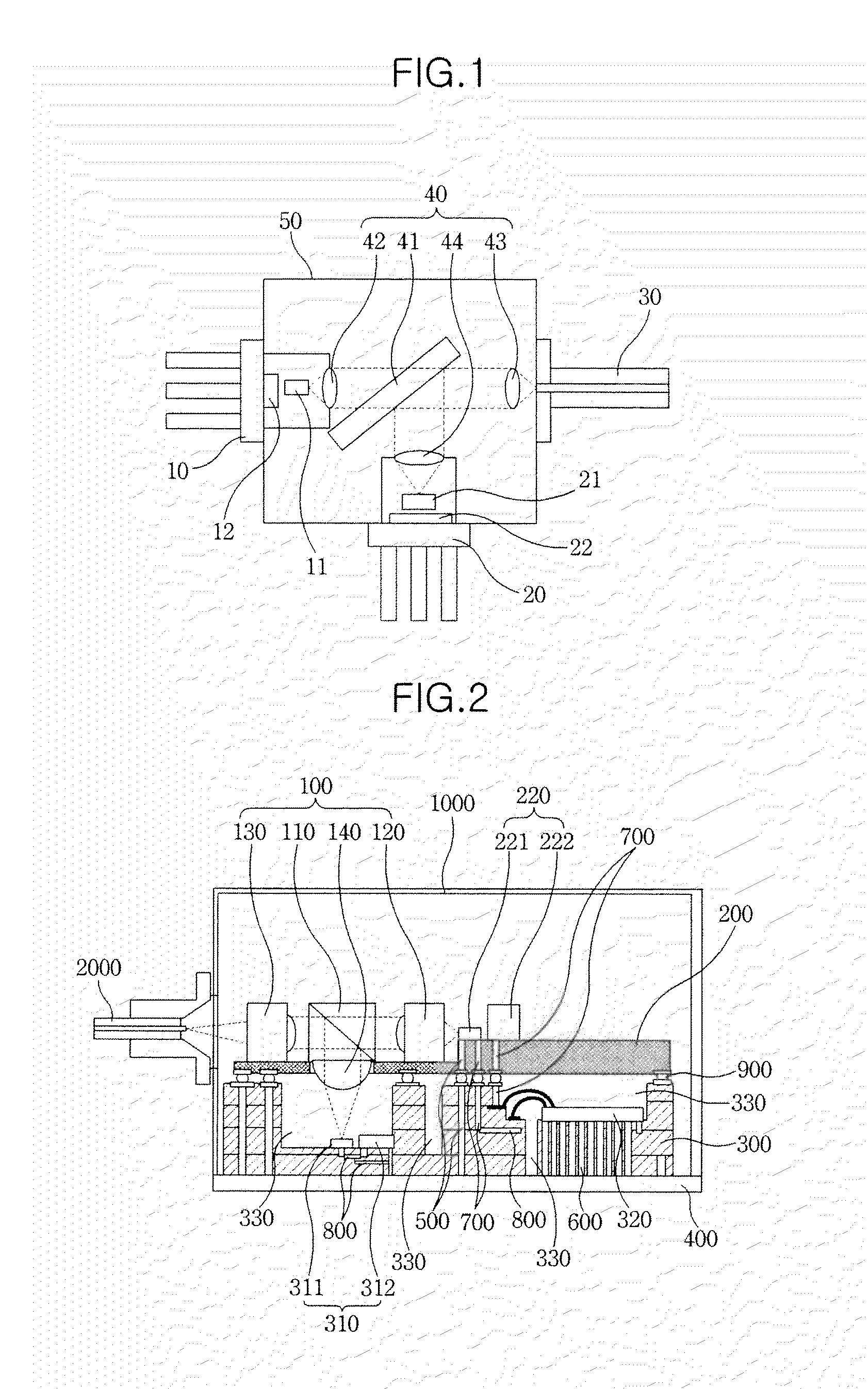
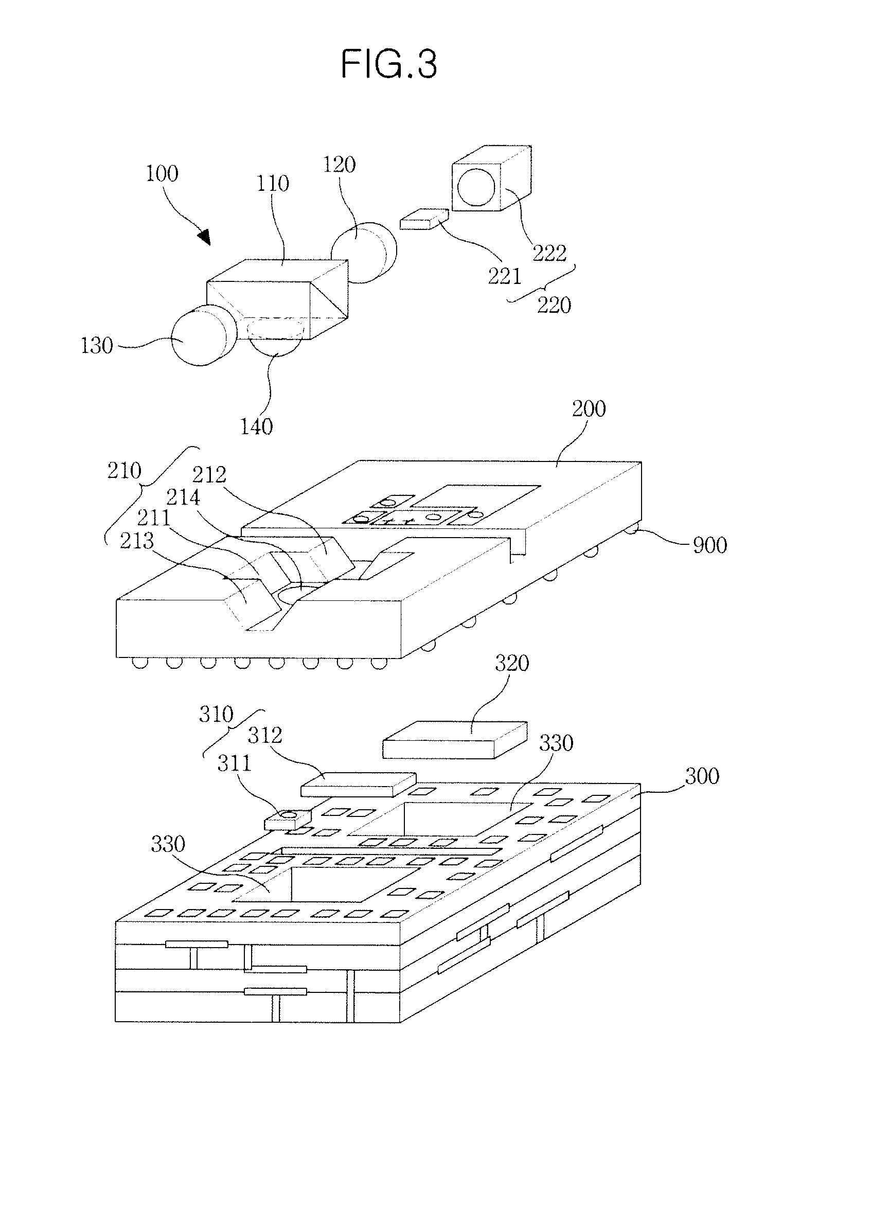
[0032]FIG. 2 is a cross-sectional view illustrating a bidirectional optical transceiver according to an exemplary embodiment, and FIG. 3 is an exploded perspective view showing a stacked structure of the bidirectional optical transceiver. As illustrated in FIGS. 2 and 3, the bidirectional optical transceiver includes an optical system 100, an optical bench 200 and a multi-layer substrate 300.

[0033]The optical system 100 transmits an optical beam to an optical line or receives an optical beam from the optical line. An accommodating part 2...


PUM


Abstract

A bidirectional optical transceiver is disclosed. In the bidirectional optical transceiver, by implementing, as a stacked structure, an optical bench in which an optical system and an optical-transmitting module are installed and a multi-layer substrate with good thermal, electrical and high-resistance characteristics in which an optical-receiving module and a driving circuit for driving the optical-transmitting module are installed, thermal, electrical or optical crosstalk is prevented, high-speed transmission of transmission signals is possible through high-speed modulation thereof, and miniaturization is achieved.

Description

CROSS-REFERENCE TO RELATED APPLICATION[0001]This application claims the benefit under 35 U.S.C. §119(a) of Korean Patent Application No. 10-2008-96979, filed on Oct. 2, 2008, the disclosure of which is incorporated by reference in its entirety for all purposes.BACKGROUND[0002]1. Field[0003]The following description relates to a bidirectional optical transceiver, and more particularly, to a technology for preventing thermal, electrical or optical crosstalk in a bidirectional optical transceiver which provides reception and transmission using one optical line.[0004]2. Description of the Related Art[0005]In a passive optical network, such as a Gigabit PON (GPON), an Ethernet PON (EPON), a Wavelength Division multiplexing PON (WDPON) and so on, an Optical Network Unit (ONU) and Optical Line Terminal (OLT) each includes an optical-transmitting module and an optical-receiving module. A bidirectional optical transceiver is an apparatus in which an optical-transmitting module and an optical...

Claims


Application Information

Patent Timeline
Patent Type & Authority Applications(United States)
IPC IPC(8): H04B10/00G02B6/42H01S5/022
CPCH04B10/40H01L2224/48091H01L2224/49109H01L2924/3011H01L2924/00014H01L2924/00H01L2924/30111H04B10/25
Inventor LEE, JONG-JINKANG, HYUNG-SEOKOH, JAI-SANG
Owner ELECTRONICS & TELECOMM RES INST
Why Eureka
Try Eureka