Surface Treatments for Turbine Components to Reduce Particle Accumulation During Use Thereof

a turbine and surface treatment technology, applied in the direction of liquid fuel engine components, wind turbines with parallel air flow, perpendicular air flow, etc., can solve the problems of frequent maintenance related shutdown of turbine components, lack of erosion or corrosion resistance of martensitic stainless steel, etc., and achieve the effect of preventing micropitting

Inactive Publication Date: 2010-04-08
GENERAL ELECTRIC CO
View PDF12 Cites 30 Cited by
  • Summary
  • Abstract
  • Description
  • Claims
  • Application Information

AI Technical Summary

Benefits of technology

[0006]Disclosed herein are surfaces of turbine engine components and methods that substantially prevent micropitting as a result of particle impact during use. In one embodiment, the surface of a turbine engine component that is resistant to sand fouling comprises a substrate; and a carbide and / or nitride coating deposited thereon, wherein the coated surface has a roughness (Ra) of less than 12 microinches.
[0007]A method for substantially preventing micropitting on a surface of a turbine engine component, comprises treating the surface of the turbine engine component to provide an average roughness (Ra) of less than 12 microinches; and depositing a nitride and / or a carbide coating onto the treated surface at a thickness of less than 50 microns by electron beam physical vapor deposition, cathodic arc evaporation, or magnetron sputtering.
[0008]In another embodiment, a method for substantially preventing micropitting on a surface of a turbine engine component comprises depositing a nitride and / or a carbide coating onto the surface at a thickness of less than 50 microns by electron beam physical vapor deposition, cathodic arc evaporation, or magnetron sputtering; and treating the coated surface of the turbine engine component to provide an average roughness (Ra) of less than 12 microinches.
[0009]The disclosure may be understood more readily by reference to the following detailed description of the various features of the disclosure and the examples included therein.

Problems solved by technology

Existing base materials for turbine components such as, but not limited to, martensitic stainless steels do not have adequate erosion or corrosion resistance under these conditions.
The severe erosion that can result may damage the turbine components, thereby contributing to frequent maintenance related shutdowns, loss of operating efficiencies, and the need to replace various components on a regular basis.
In addition to erosion and corrosion, sand fouling has recently emerged as a key factor significantly degrading performance in turbine components.
For example, aircraft engines flying domestic routes often experience significant sand fouling due to heavy sand intake during flight idle, take off, and landing.
Specifically, this increased roughness results from the formation of micropits due to particle impact.
High temperatures in the downstream stages of the compressor result in baking of the sand particles, which increases the airfoil-sand adhesion.
Consequently, water wash as is frequently used to clean the turbine components is not successful in removing the accumulated sand particles.
These processes produce as-deposited coatings with relatively rough surface textures and limited hardness, which can have adverse affects on the performance of the turbine.
Moreover, erosion, if any, of such coatings significantly degrades the surface roughness, accelerating sand fouling.
In addition, these processes can produce coatings that can adversely affect the high cycle fatigue strength of the substrate or base material.
Finally, the coatings produced by these processes often require modification to the turbine airfoil to compensate for the thickness of the coatings.

Method used


Image

  • Surface Treatments for Turbine Components to Reduce Particle Accumulation During Use Thereof
  • Surface Treatments for Turbine Components to Reduce Particle Accumulation During Use Thereof
  • Surface Treatments for Turbine Components to Reduce Particle Accumulation During Use Thereof

Examples


Embodiment Construction

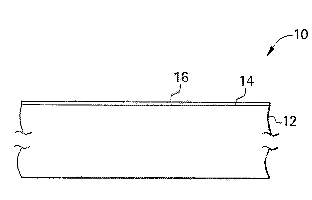
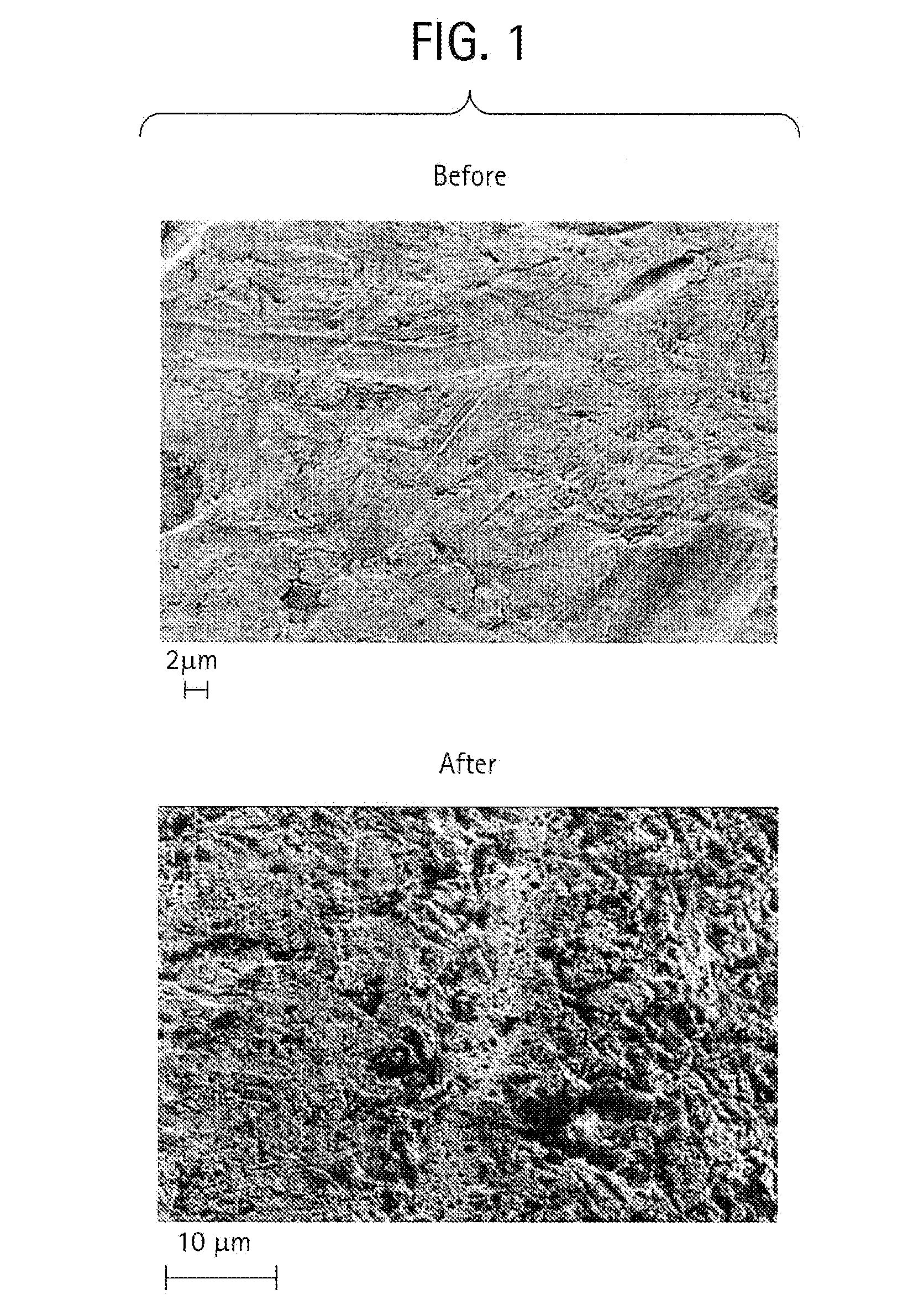
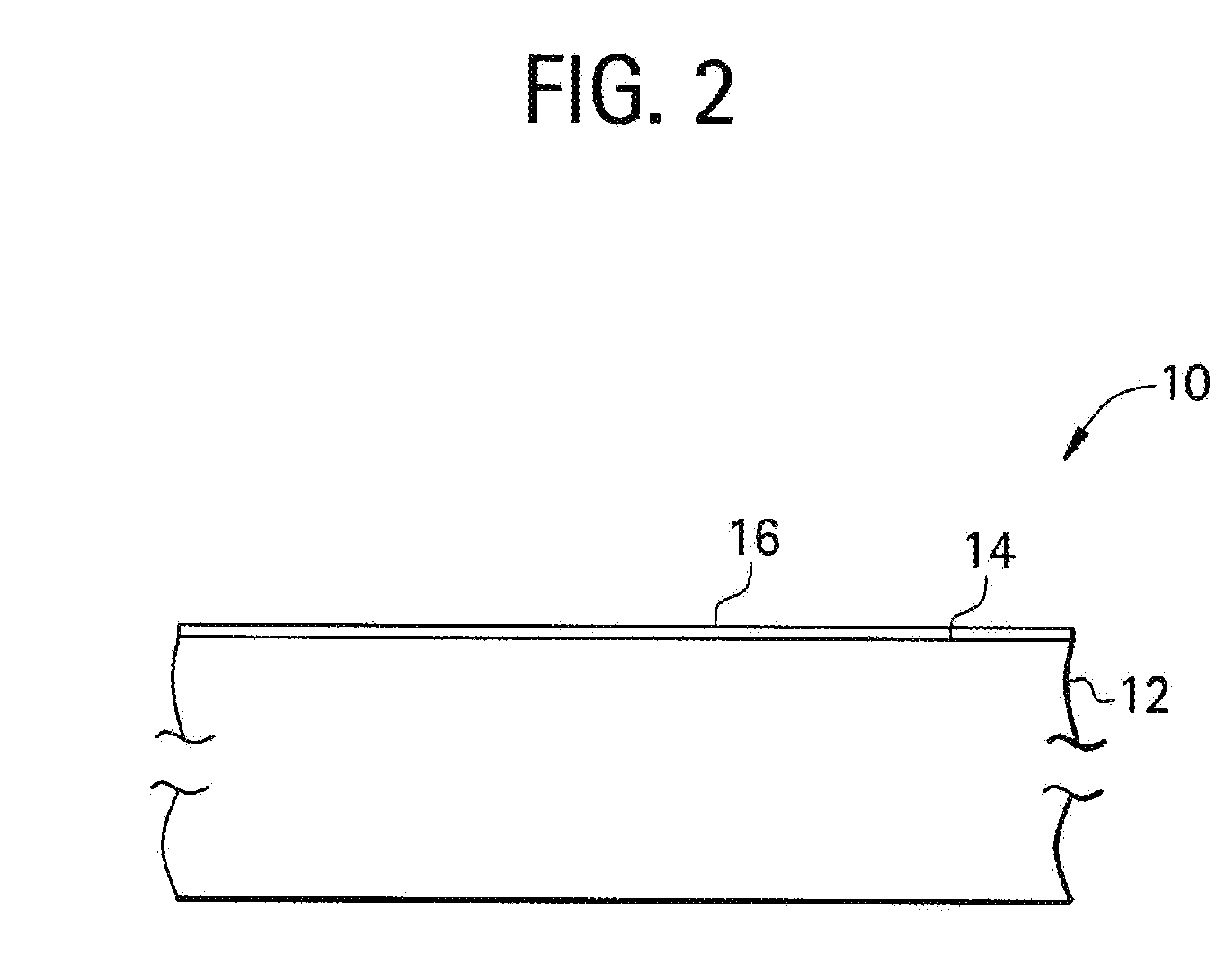
[0017]It has been discovered through characterization of fouled turbine components that sand accumulates in micropits formed as a result of the impact of particles, e.g., sand. For example, FIG. 1 illustrates a turbine component surface and the extent of micropit formation caused by the impact of sand particles. FIG. 1 provides a surface comparison of a new turbine blade component relative to a used turbine blade component subjected to sand fouling, wherein both surfaces were treated with the same cleaning solution to remove buildup from the surface. Evidence of micropitting was clearly distinguishable in the surface of the used turbine blade component. Although not shown, prior to treatment with the cleaning solution to remove buildup, sand accumulation was evident on the surfaces of the used turbine blade component. Disclosed herein are surface treatments for a turbine engine component so as to reduce sand accumulation and / or erosion caused by the impact of particles on the turbin...


PUM

PropertyMeasurementUnit
thicknessaaaaaaaaaa
thicknessaaaaaaaaaa
sizesaaaaaaaaaa

Abstract

A turbine engine component includes at least one treated surface wherein the treated surface has a surface roughness (Ra) of less than 12 microinches; and a hard coating disposed on the superfinished surface, wherein the hard coating is a nitride and/or a carbide material at a thickness of less than 50 microns formed using electron beam physical vapor deposition, cathodic arc evaporation, or magnetron sputtering. disclosed are methods for substantially preventing micropitting on a surface of a turbine engine component.

Description

BACKGROUND[0001]The present disclosure generally relates to turbine engine components having surface treatments effective to reduce particle accumulation during use.[0002]Metal components are used in a wide variety of industrial applications, under a diverse set of operating conditions. Existing base materials for turbine components such as, but not limited to, martensitic stainless steels do not have adequate erosion or corrosion resistance under these conditions. The severe erosion that can result may damage the turbine components, thereby contributing to frequent maintenance related shutdowns, loss of operating efficiencies, and the need to replace various components on a regular basis. In many cases, the components are provided with coatings, which impart various characteristics, such as corrosion resistance, heat resistance, oxidation resistance, and erosion resistance. As an example, erosion-resistant coatings are frequently used on the first stages of high pressure and interm...

Claims


Application Information

Patent Timeline
Patent Type & Authority Applications(United States)
IPC IPC(8): F01D9/02F01D5/14F01D25/24C23C14/35
CPCC23C14/028C23C14/0641Y02T50/67F05C2251/10F05B2230/313F05D2260/607F05D2300/611Y02T50/60
Inventor VARANASI, KRIPA KIRANBHATE, NITINCARROLL, MICHAEL DAVIDGHASRIPOOR, FARSHADKULKARNI, AMBARISH JAYANTROSENZWEIG, LARRY STEVENSCHELL, JERRY DONALDZHONG, DALONG
Owner GENERAL ELECTRIC CO
Why Eureka
Try Eureka