Supercharge Your Innovation With Domain-Expert AI Agents!

High temperature bd development for memory applications

a memory application and high temperature technology, applied in the direction of coatings, chemical vapor deposition coatings, metallic material coating processes, etc., can solve the problems of dielectric films outgasping volatile species and shrinking, and achieve the effect of increasing the flow rate of one or more organosilicon compounds

Inactive Publication Date: 2010-04-08
APPLIED MATERIALS INC
View PDF8 Cites 7 Cited by
  • Summary
  • Abstract
  • Description
  • Claims
  • Application Information

AI Technical Summary

Benefits of technology

The patent describes methods for depositing a memory device using a dense low-k dielectric film with terminal methyl groups. The method involves depositing the film by reacting a gas mixture containing a silicon precursor, a carbon precursor, and an oxygen precursor at a high temperature. The film is then opened and filled with a conductive material. The methods also involve sequentially depositing a silicon oxide layer with low carbon content and a carbon doped silicon oxide layer with high carbon content without plasma arcing. The variations in process conditions reduce the variation in DC bias of the powered electrode during processing. The methods can be used to form a memory device with improved performance.

Problems solved by technology

Processes for fabricating memory devices, however, feature subsequent high-temperature steps that cause the dielectric film to out-gas volatile species and shrink.

Method used


Image

  • High temperature bd development for memory applications
  • High temperature bd development for memory applications
  • High temperature bd development for memory applications

Examples


examples

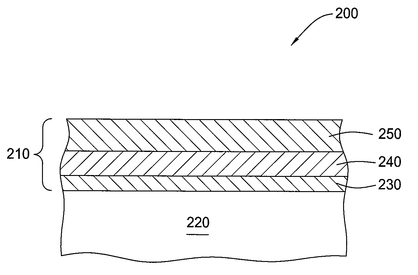
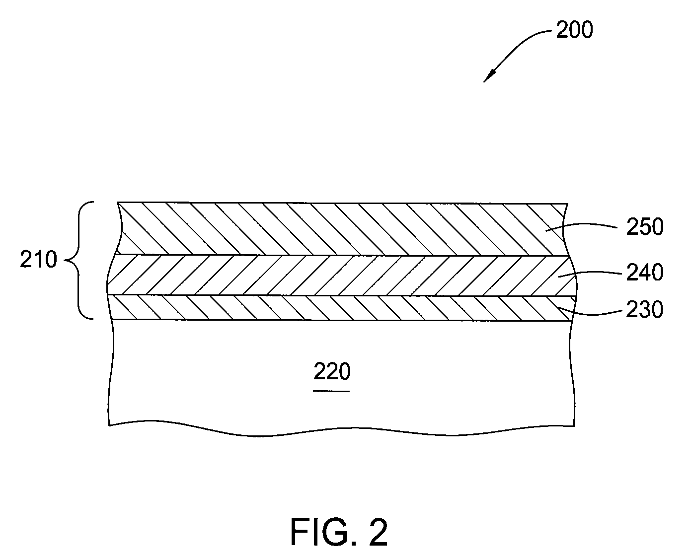
[0050]Organosilicate dielectric layers were deposited on a substrate in accordance with the embodiment described above with respect to FIG. 5. The films were deposited using a PECVD chamber (i.e., CVD chamber) on a PRODUCER system, available from Applied Materials, Inc. of Santa Clara, Calif. During deposition the chamber pressure was maintained at a pressure of about 4.5 Torr and the substrate was maintained at a temperature of about 350° C.

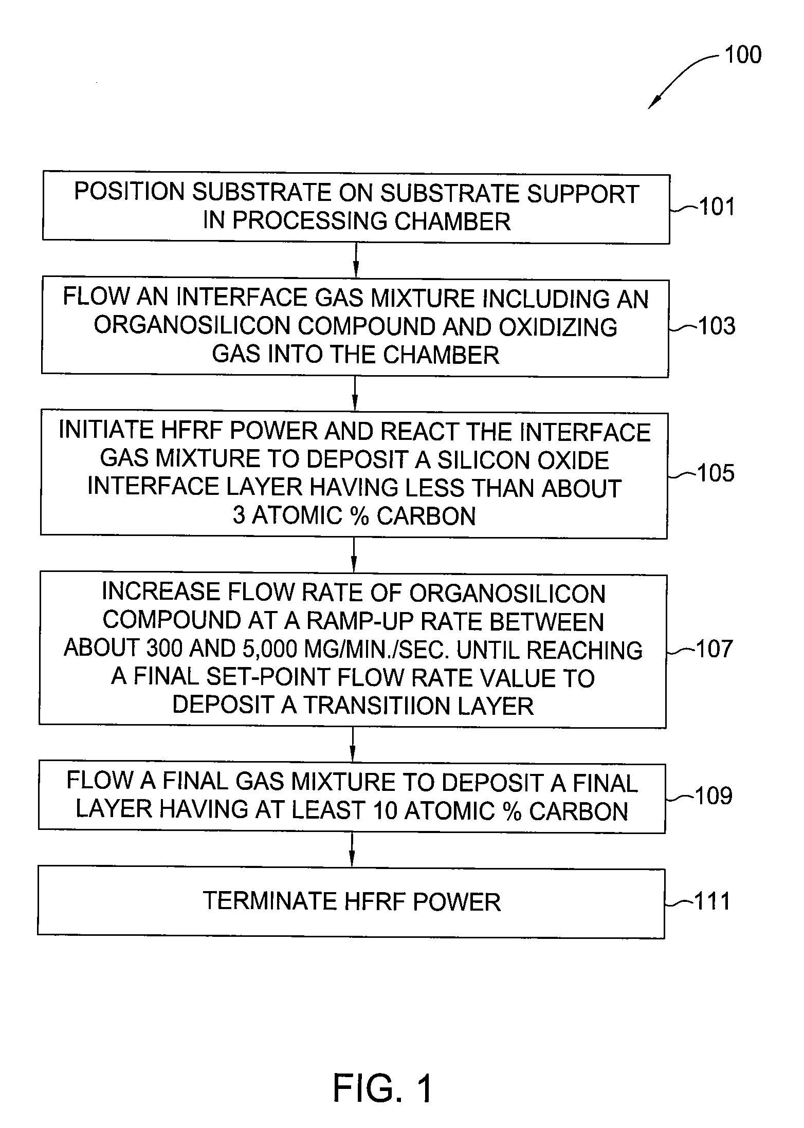
[0051]The substrate was positioned on a substrate support disposed within a process chamber. The process gas mixture having an initial gas composition of 1000 sccm helium and 700 sccm oxygen for the interface layer was introduced into the chamber and flow rates stabilized before initiation of the HFRF power. Subsequently, HFRF power of about 500 W was applied to the showerhead to form a plasma of the interface process gas mixture composition including a OMCTS flow rate of about 700 mg / min., and deposit a silicon oxide layer having a carbon conte...


PUM

PropertyMeasurementUnit
temperatureaaaaaaaaaa
dielectric constantaaaaaaaaaa
temperatureaaaaaaaaaa

Abstract

A method and apparatus for depositing organosilicate dielectric layers having good adhesion properties and low dielectric constant. Embodiments are described in which layers are deposited at low temperature and at high temperature. The low temperature layers are generally post-treated, whereas the high temperature layers need no post treating. Adhesion of the layers is promoted by use of an initiation layer.

Description

BACKGROUND OF THE INVENTION[0001]1. Field of the Invention[0002]Embodiments of the present invention generally relate to the fabrication of integrated circuits. More particularly, embodiments of the present invention relate to a process for depositing low dielectric constant layers on a substrate.[0003]2. Description of the Related Art[0004]Integrated circuit geometries have dramatically decreased in size since such devices were first introduced several decades ago. Since then, integrated circuits have generally followed the two year / half-size rule (often called Moore's Law), which means that the number of devices on a chip doubles every two years. The continued reduction in device geometries has generated a demand for inter layer dielectric films having lower dielectric constant (k) values because the capacitive coupling between adjacent metal lines must be reduced to further reduce the size of devices on integrated circuits.[0005]Much research has been devoted to improving the per...

Claims


Application Information

Patent Timeline
Patent Type & Authority Applications(United States)
IPC IPC(8): H01L21/4763H01L21/31
CPCC23C16/0272C23C16/029C23C16/401C23C16/56H01L21/76801H01L21/02216H01L21/02274H01L21/31633H01L21/02126
Inventor LAKSHMANAN, ANNAMALAIMANALO, DANTERAJAGOPALAN, NAGARAJANSCHMITT, FRANCIMAR C.KIM, BOK HOEN
Owner APPLIED MATERIALS INC
Features
  • R&D
  • Intellectual Property
  • Life Sciences
  • Materials
  • Tech Scout
  • Unparalleled Data Quality
  • Higher Quality Content
  • 60% Fewer Hallucinations
Learn More