
Pleated multi-layer filter media and cartridge

a filter media and multi-layer technology, applied in the field of pleated filter media, can solve the problems of brittleness, unable to withstand elongation, and limited maximum surface area and media packing density,

Inactive Publication Date: 2010-04-15
3M INNOVATIVE PROPERTIES CO
View PDF59 Cites 13 Cited by
  • Summary
  • Abstract
  • Description
  • Claims
  • Application Information

AI Technical Summary

Benefits of technology

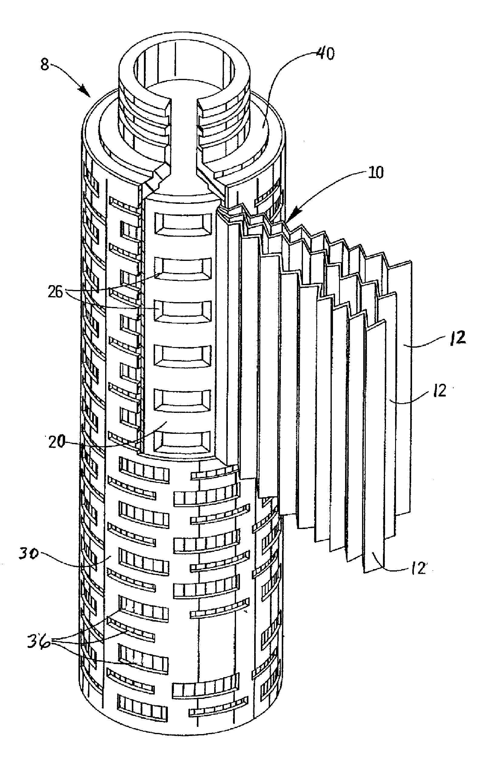
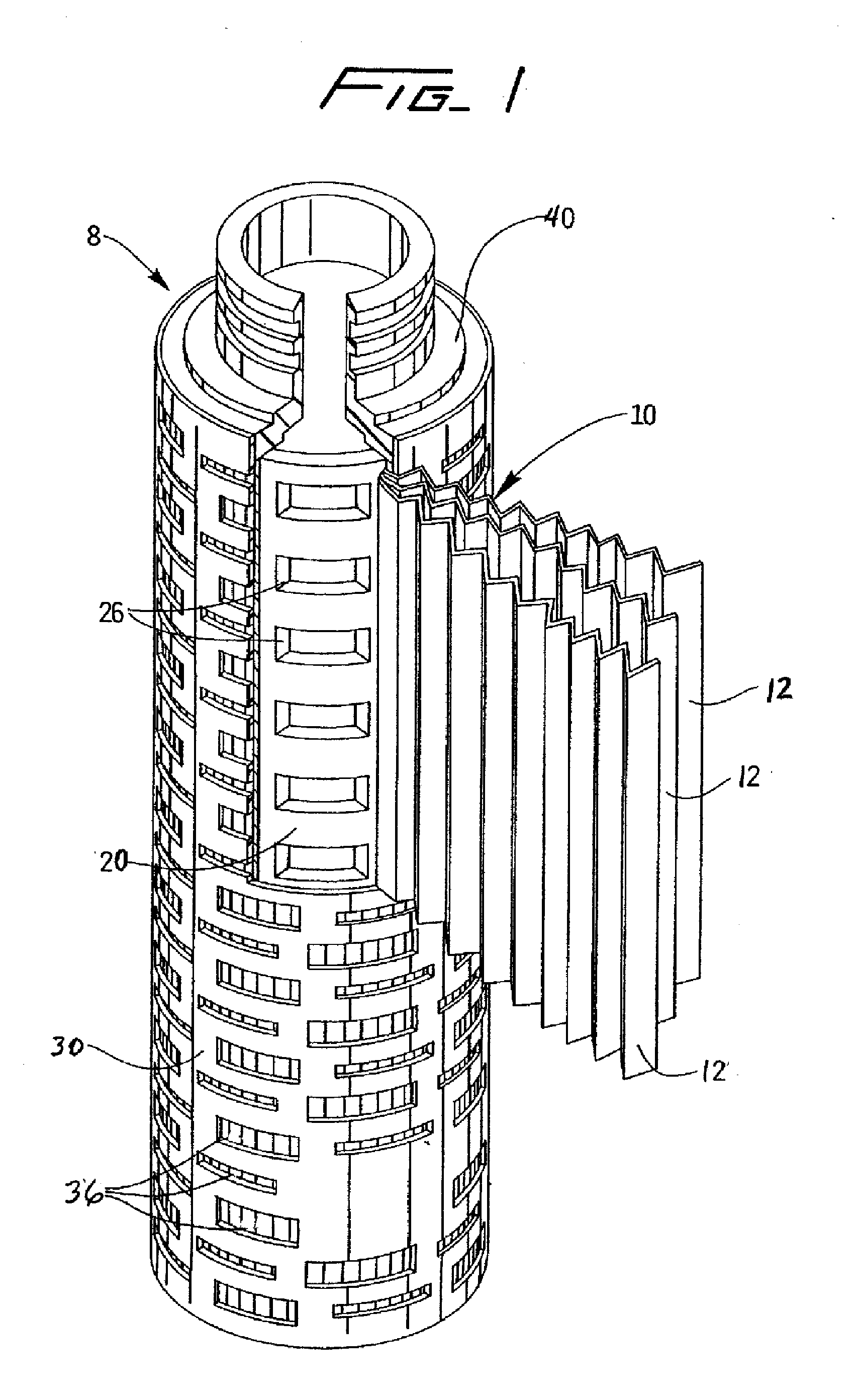
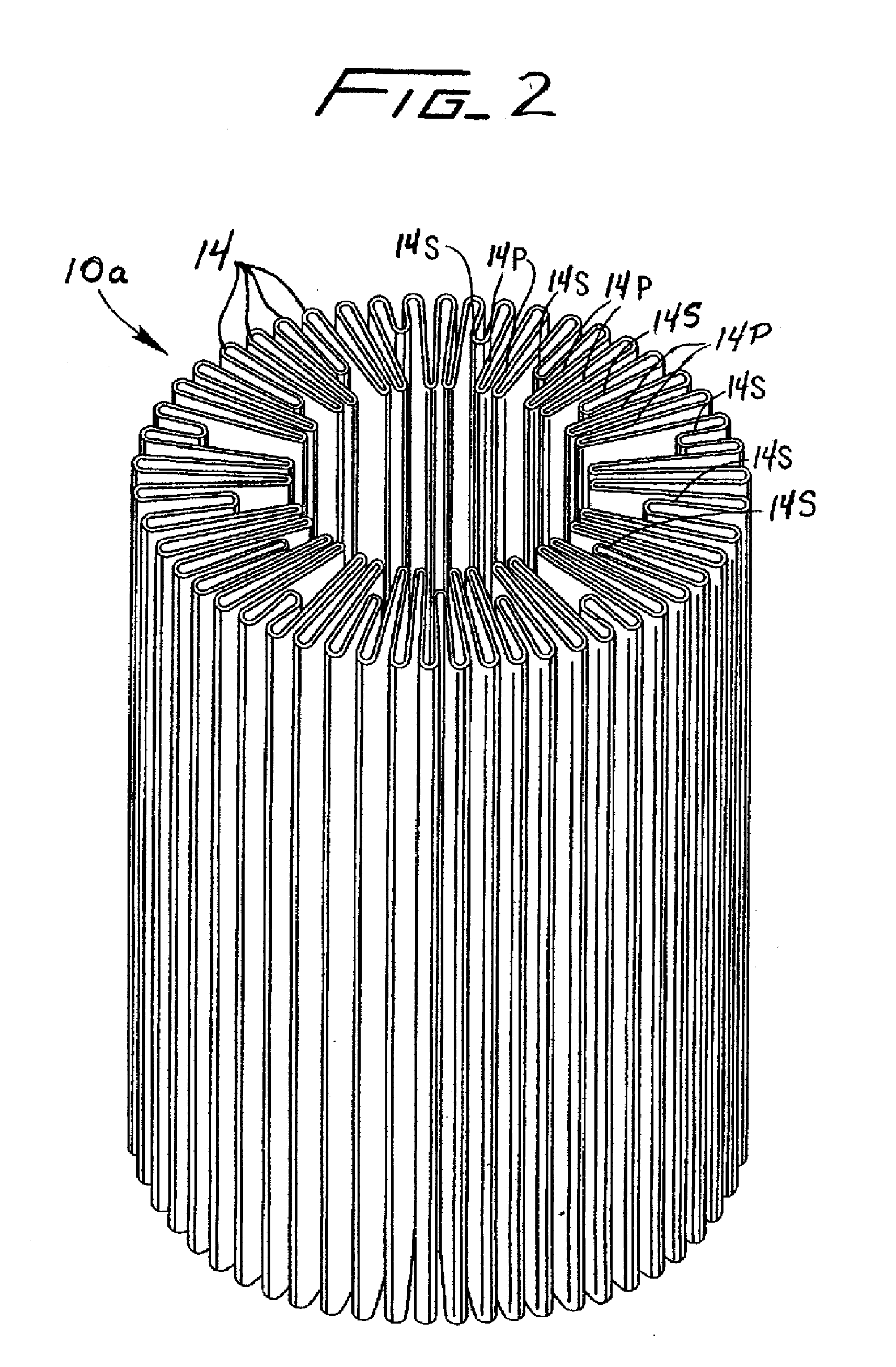
[0145]As is evident from a review of Tables I and II where the pleated filter element of the present disclosure having the advanced pleat technology is compared to two of the lenticular style cartridges, the advantages of the pleated filter element of the present disclosure become more apparent. In Table I the pleated filter element of the present disclosure is compared to the best known lenticular cartridge design believed presently available. As evident, the first embodiment representing the pleated filter element of the present disclosure is clearly a better engineered device than the lenticular cartridge of the prior art when built to the same physical dimensions, as the DCI is about 0.54 whereas the DCI for the lenticular cartridge is about 0.34. Consequently, the DCI of about 0.34 is the highest known DCI for a lenticular cartridge believed attainable, thus far. It is believed that the pleated filter element of the present disclosure, can achieve a DCI value of up to about 0.64. It is further believed that the pleated filter element of the present disclosure is best utilized when the DCI thereof is between about 0.35 to about 0.64. The DCI is a comparative index that normalizes the cartridges to be compared based on their total cartridge dry weight, and the physical volume each cartridge occupies in space. These two factors contribute to the ease of use and space saving considerations, because to get a larger DCI value, one needs to have either or both smaller volume and lighter components. Other factors included in the DCI are the total effective media mass, total effective surface area, and the total effective thickness of the media. Again, to achieve a higher DCI value, a cartridge has to have high amounts of media, surface area and total depth. Media mass is one indication that the cartridge will perform better than any alternative considered because it is believed that, with a higher mass, there is a higher concentration of adsorptive particulates. These adsorptive particulates contribute to the adsorptive function of the depth media by providing more charge sites. In addition to the media mass the DCI also considers area. The more surface area a filter has the better the filter performance that can be expected. With a larger surface area, assuming process flow rates remain constant, the flux is reduced. Flux, as expressed as flow rate per unit area, is influential in determining the contact time the fluid has with the charge sites. Obviously, a lower flux means longer contact times, thus, enabling the depth media to be more efficient. Another influential factor concerning contact time is media depth or thickness. The DCI also considers thickness. The thicker the depth media is the more contact time the fluid to be filtered has with the charged sites in the media. This longer contact time will enable a more efficient filtration. In Table I, it is again clear that the other comparative indexes are also higher for the pleated filter element of the present disclosure when compared to the particular evaluated lenticular design. As can be seen, the Gk factor is about 6.28, the MUI is about 427, the MPD is about 12.87 for the describe representative embodiment of the pleated filter element of the present disclosure, where as the lenticular cartridge yields a Gk factor of about 4.78, an MUI of about 220, an MPD of about 11.25, and a MPD of about 11.25. All of these comparison factors and indexes indicate that the pleated filter element of the present disclosure is a better over all design compared to the lenticular cartridge of Table I. The greater indexes values recorded for the pleated filter element of the present disclosure suggests that the pleated filter element of the present disclosure will be more efficient since it has a greater surface area and a greater effective media mass. For this comparison purposes the volume of the cartridge was kept the same, however, it is important to note that because of the simplicity of the design, (having less parts), the total dry weight of the cartridge can be reduced, thus giving a higher DCI value. Again the DCI can be expressed in terms of DCI 2 where the effective mass of the media is replaced by mass of total particulate adsorbers. This change would not lead to the same conditions for this comparison since it is believed that both cartridges will not have the same percent mass of particulate adsorbers. The DCI 2 will be more evident in other design comparisons especially in Table III.

Problems solved by technology

For a given filter volume displacement of a lenticular-type filter unit composed of a plurality of lenticular cells, the maximum surface area and media packing density are limited due to the thickness of support separators found inside the cells and the space between cells necessary to permit acceptable flow rate.
These surface-type filter media lack the highly desirable particulate adsorbers found in adsorptive depth filter media.
However, adsorptive depth-type filter media, which incorporate such particulate matter, are brittle and typically cannot withstand the elongation at the bend radii when pleated.
The cracking is a result of the filter media's structure and its rigidity caused by the high amounts of diatomaceous earth (DE).
Also, because the internal bend radius is significantly smaller than the neutral bending radius, there is a high degree of compressive strain along the internal bend radius.
Cracking and splitting of the fibers in the filter media is the inevitable result of these high strains because the filter media contains high amounts of particulate adsorbers and low amounts of cellulose.
The thicker the filter media, the greater the difference is between external and internal bending radius, leading to high filter media elongation at the external radius and high filter media compression at the internal radius.
Thus, pleating conventional adsorptive depth filter media causes the filter media to crack or tear, thereby losing both filtering ability and structural integrity.
Typically, however, there is a trade-off between achieving these desirable filter characteristics.
The present state of the art does not allow the use of adsorptive depth filter media in high media density pleat designs, such as disclosed in Olsen, and as a result high media packing density has not been achieved in adsorptive depth-type filter modules.
The present art also has problems associated with wet weight.
After the lenticular cartridges are used the added weight due to the media being wet makes it cumbersome to handle.
Another problem with the lenticular style cartridges becomes the size, when larger quantities of fluid need to be filtered, larger diameter lenticular cartridges are used, these lenticular cartridges both use more floor space and also makes it more difficult to handle due to cartridge size.

Method used


Image

  • Pleated multi-layer filter media and cartridge
  • Pleated multi-layer filter media and cartridge
  • Pleated multi-layer filter media and cartridge

Examples


example embodiment

[0068]In accordance with one specific representative embodiment of the depth filter media, a method of forming a filter element is herein described. The individual depth filter media layers are formed by making about a 1% slurry using water that has been treated by reverse osmosis to improve its purity (RO water). A typical slurry solution consists of commercially available Kraft pulp, about 6% refined pulp (about −250 CSF, Canadian Standard Freeness, as described in U.S. Pat. No. 4,305,782) and about 68% diatomaceous earth by dry weight, as would be known by one skilled in the art. In one representative formulation two types of resin, such as, for example, the representative charge modifying recipe as disclosed in U.S. Pat. No. 5,085,784 with chemical structures as further disclosed in U.S. Pat. No. 4,473,474, the disclosure of each is herein incorporated by reference to the extent not inconsistent with the present disclosure, are added at about 5.2% and about 1.3% by weight resin ...

example 1

[0149]In a specific example of media forming the individual depth filter media layer were formed by making about a 1% slurry using water that has been treated by reverse osmosis to improve its purity (RO water). The slurry solution consisted of about 26.8% commercially available Kraft pulp, about 7.3% refined pulp (about −250 CSF, Canadian Standard Freeness, as described in U.S. Pat. No. 4,305,782) and about 65.9% 0.02 D'Arcy's diatomaceous earth (World Minerals Celite 507) by dry weight, as would be known by one skilled in the art. A Polyamine-Epichlorohydrin Resin (Hercules Polycap 1884) was added at about 1.5% by weight resin solids on slurry solids.

[0150]The resultant slurry was fed into a papermaking machine (Fourdrinier type). The slurry was laid down at a constant thickness on to a moving screen. The screen speed for this process was about 3 ft / min. The screen was over vacuum slots to remove most of the RO water from the slurry. The applied vacuum pressures ranged from about ...

example 2

[0158]The unpleated flat stock, as described in the specific example (Example 1) media, was cut into a 47 mm disk using a dye from each of the rolls used previously to make the filter cartridge composed of the filter module and the pleated filter element. The filter disks were then placed in to a Cuno 47 mm housing Part number 70225-01 where the media were placed in the same order as in the way the rolls were used to create the filter element as described previously and the housing was sealed. This process was repeated for 1 additional housing resulting in 2 housings assembled in the same manner. Using a flow of 45.4 ml / min resulting on a flux of 37.5 liters per minute per square meter, the filters were challenged with 0.16 g / L Grandma's Molasses—“Robust Flavor” (Green Label) brand molasses dispersed in water. The pressure drop across the filter was monitored and the test was stopped when a pressure differential of 25 PSID was recorded across the filters. The resulting throughput fo...


PUM


Abstract

A pleated filter element includes a composite depth filter medium formed into a plurality of pleats. The composite depth filter medium includes a plurality of depth filter media layers. Each of the plurality of depth filter media layers includes adsorber particulate matter. Each of the plurality of depth filter media layers may have a thickness less than about 1300 microns. The plurality of depth filter media layers may have at least 50% by weight of adsorber particulate matter.

Description

RELATED APPLICATIONS[0001]This application is a continuation of U.S. application Ser. No. 11 / 250,275 of Hamlin et al., filed on Oct. 14, 2005, which claims the benefit of U.S. Provisional Application Ser. No. 60 / 619,353 of Hamlin et al., filed on Oct. 15, 2004, the disclosure of which is herein incorporated by reference in its entirety.BACKGROUND OF THE DISCLOSURE[0002]The present disclosure relates in general to pleated filter media and, in particular, to pleated adsorptive depth filter media for filtering fluids and to the filter cartridges utilizing such pleated filter media.[0003]Filtration is the process of separating particles or contaminants from a fluid (liquid or gas), and can be accomplished by passing the fluid through porous filter media that stops or captures the particles while permitting the fluid to pass therethrough. Most conventional filter media may be categorized into two broad categories: surface-type filter media, which stops fluid contaminants on its surface, ...

Claims


Application Information

Patent Timeline
Patent Type & Authority Applications(United States)
IPC IPC(8): B01D27/06B23P11/00
CPCB01D29/21B01D46/0036B01D46/2411B01D46/522Y10T29/49428B01D2201/122B01D2201/182B01D2275/10B01J20/14B01D2201/0407Y10T442/60
Inventor HAMLIN, THOMAS J.KURUC, GOKHANLEAVESLEY, PETER J.SALE, RICHARD D.
Owner 3M INNOVATIVE PROPERTIES CO
Learn More