Time resolved fluorescent imaging system

a fluorescent imaging and time-resolved technology, applied in the field of time-resolved fluorescent imaging systems, can solve the problems of fp assays not being able to detect changes in the structure of a large protein, the ssf method suffers, and the removal of spectral filtering is not very effective, so as to reduce the scattering of excitation light

Inactive Publication Date: 2010-04-15
GE HEALTHCARE BIO SCI CORP
View PDF6 Cites 42 Cited by
  • Summary
  • Abstract
  • Description
  • Claims
  • Application Information

AI Technical Summary

Benefits of technology

[0015]The present invention has been accomplished in view of the above-mentioned cost and technical background, and it is an object of the present invention to pr

Problems solved by technology

Because of its composite nature, spurious fluorescence generally occurs over a broad range of wavelengths and its removal by spectral filtering is not very effective.
The SSF method suffers because of two reasons: (a) The signal depends on the intensity of the excitation source, and the design details of the optical measuring instrument.
As a result such FP assays can not detect changes to the structure of a large protein, because the rotational time scales would be too long to affect the polarization of fluorescence.
Lack of sensitive time-resolved imaging systems has hampered the development of novel assays for the study of in-situ protein folding dynamics (Lakowicz J R,

Method used


Image

  • Time resolved fluorescent imaging system
  • Time resolved fluorescent imaging system
  • Time resolved fluorescent imaging system

Examples


Embodiment Construction

[0029]The presently preferred embodiments of the invention are described with reference to the drawings, where like components are identified with the same numerals. The descriptions of the preferred embodiments are exemplary and are not intended to limit the scope of the invention.

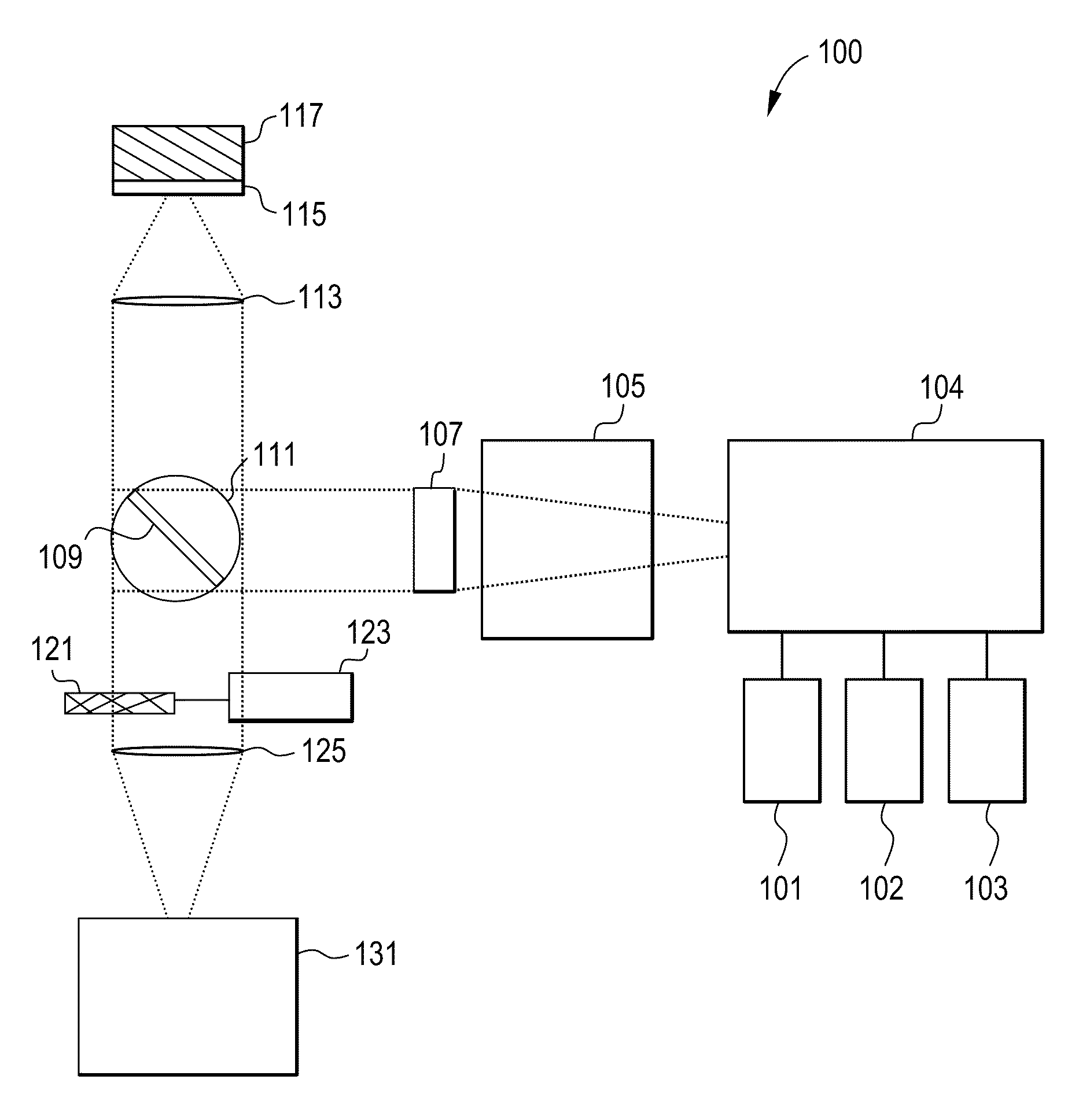
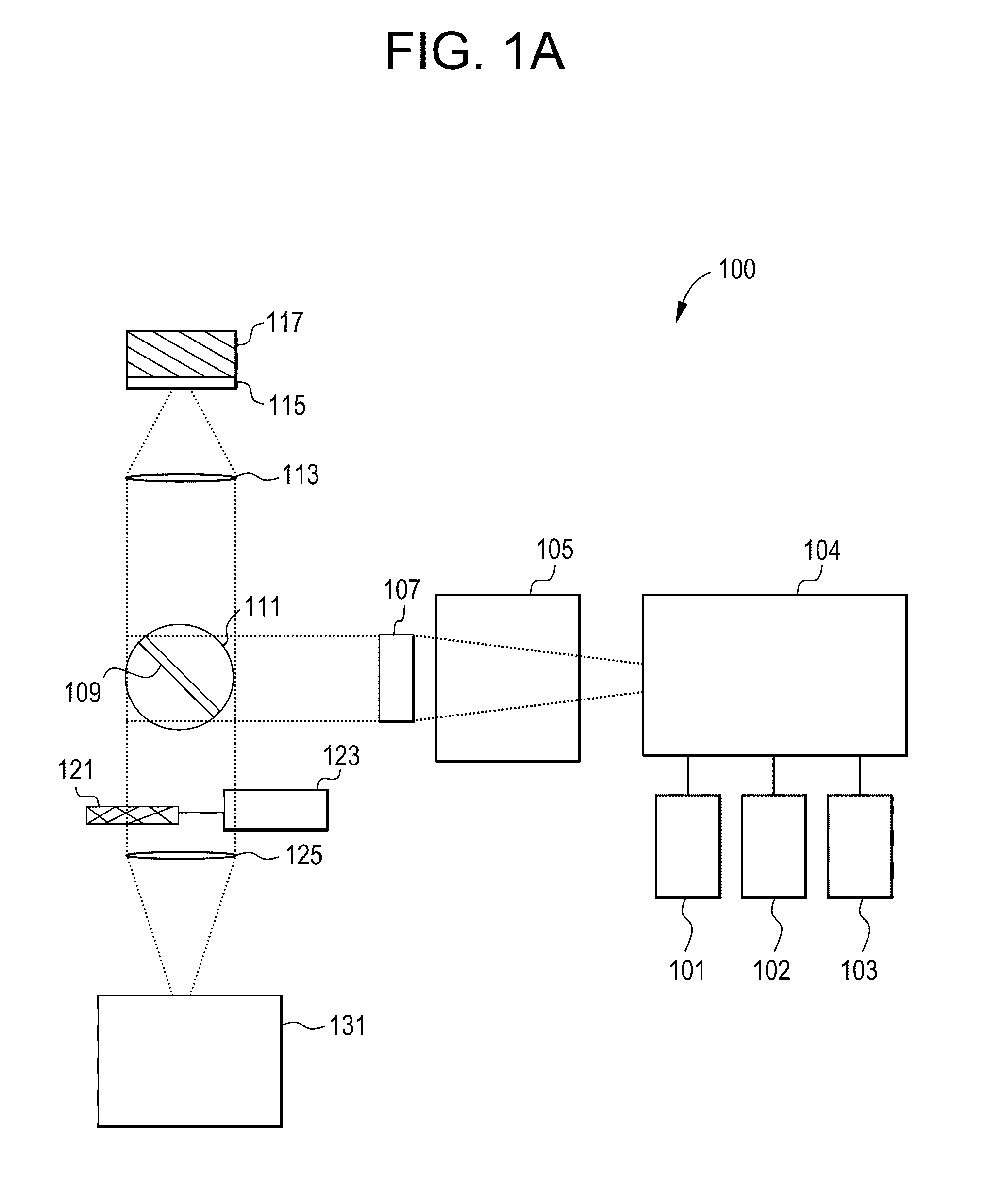
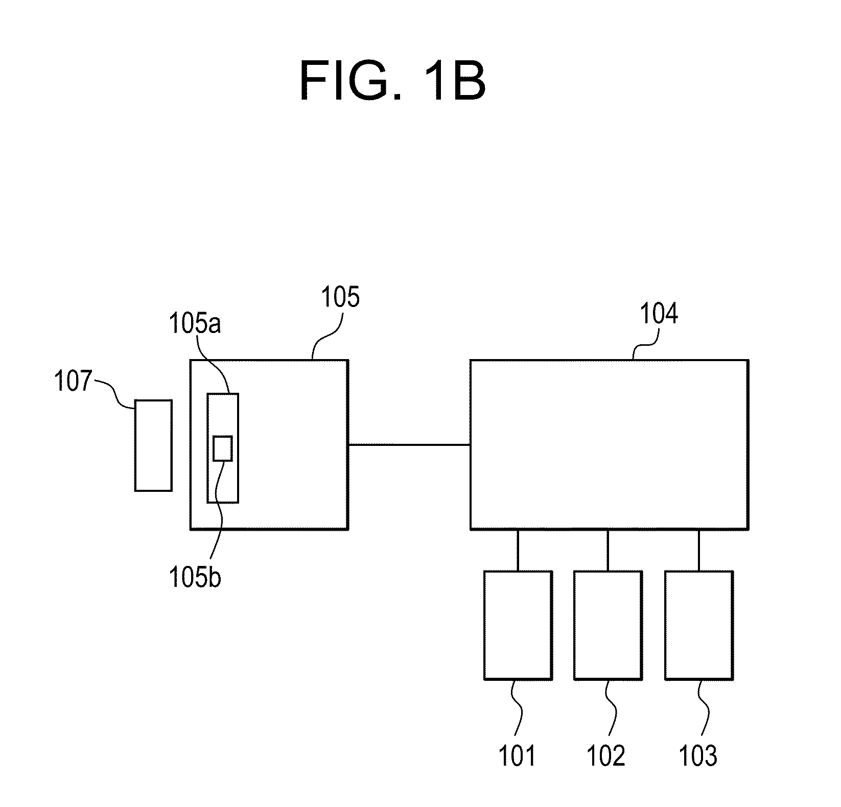
[0030]A Time Resolved Fluorescent Imaging system or a Fluorescent Lifetime Imaging system 100 is schematically presented in FIG. 1A and includes one or more light sources 101, 102 and 103 to excite a fluorescent (or fluorescently stained or labeled) target 117 or sample 117 and one or more detectors 131 to detect fluorescent emissions. The system 100 may contain other components that will ordinarily be found in fluorescent microscopes, which will be described in more detail. For a number of the components there are multiple potential embodiments. In general, the preferred embodiments of the invention depend upon the target application. For the purpose of this document the preferred target application is a...


PUM


Abstract

This invention provides a system and method that allows for time-resolved fluorescent imaging of fluorescent samples. The user is able to receive temporally filtered pictures of the sample with a reduced amount of the scattered excitation light and the short lived background fluorescence. The system allows for adjustment of fluorescent gating time and delay time.

Description

CROSS-REFERENCE TO RELATED APPLICATIONS[0001]This application claims priority to U.S. provisional patent application No. 60 / 887,230 filed on Jan. 30, 2007; the disclosure of which in incorporated herein by reference in its entirety.FIELD OF THE INVENTION[0002]This invention relates to time resolved fluorescent imaging systems.BACKGROUND OF THE INVENTION[0003]Fluorescence detection offers one of the most sensitive methods for quantification of probe molecules in biological and material systems because it can attain near single-molecule sensitivity levels. Consequently the technique is widely used in the assaying of biochemical and cellular systems, and in particular the microscopic imaging of cell-based assay, where rich biological information is provided from multiplexed high-content data (Ramm P, “Image-based screening: a technology in transition,”Curr. Opin. Biotech. 16, 41-48 (2005); Zhou X and Wong STC, “High content cellular imaging for drug development,”IEEE Sig. Proc. Mag. 23...

Claims


Application Information

Patent Timeline
IPC IPC(8): G01J1/58
CPCG01N21/6408G01N2021/6441G01N2021/6439G01N21/6458
Inventor YEKTA, AHMADFOMITCHOV, PAVEL A.MASINO, JOSEPH
Owner GE HEALTHCARE BIO SCI CORP
Why Eureka
Try Eureka