A resistor for electric high-voltage apparatus and a method of mounting a resistor

a high-voltage apparatus and resistor technology, applied in the direction of resistor details, inductances, variable inductances, etc., can solve the problems of inability to dissipate heat to any greater extent, current passing through the resistor elements, etc., to achieve rapid cooling, increase the resistance wire length, and increase the resistor capacity

Inactive Publication Date: 2010-04-15
ABB TECH AG +1
View PDF6 Cites 15 Cited by
  • Summary
  • Abstract
  • Description
  • Claims
  • Application Information

AI Technical Summary

Benefits of technology

[0011]According to an aspect of the invention there is provided a resistor of the kind described in the preamble to claim 1 by arranging the frames so as to enclose resistor elements, which comprise spring elements formed from spirally wound resistance wire. In this way, the entire circumference of the resistance wire is surrounded by the oil in the channel and the instantaneous heating of the wire occurs uniformly since the whole surface of the resistance wire is in direct contact with the oil. Together with the subsequent effective cooling, this contributes to the high capacity of the resistor according to the invention, which is rapidly cooled down after each switching operation. By designing the resistor element in the form of spring elements, the further advantage is obtained that the length of resistance wire in the spring element may be made large. At the high voltages to which the present invention relates, the distance between the top part of the resistor and the top part of the housing, that is, the distance insulated by the oil, must be sufficient to ensure the necessary electrical insulation.

Problems solved by technology

During this time, however, the current that passes through the resistor elements in the resistor is considerable.
It is thus required that the resistor wire for a short period may absorb a large energy mass in the form of heat, since it is realized that during the short switching operation the heat is not capable of being dissipated to any greater extent outside the resistor, since the cooling takes place substantially through the passage of oil after the actual switching operation.

Method used


Image

  • A resistor for electric high-voltage apparatus and a method of mounting a resistor
  • A resistor for electric high-voltage apparatus and a method of mounting a resistor
  • A resistor for electric high-voltage apparatus and a method of mounting a resistor

Examples


Embodiment Construction

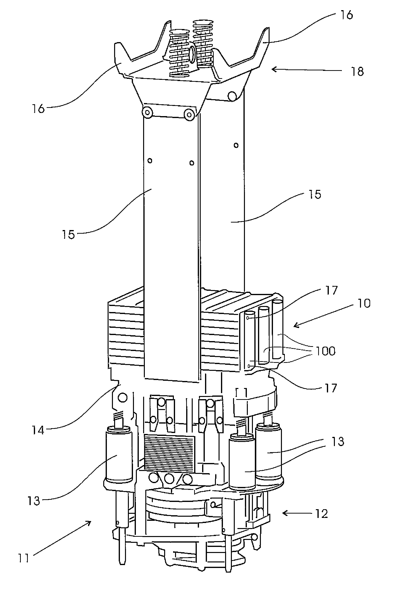
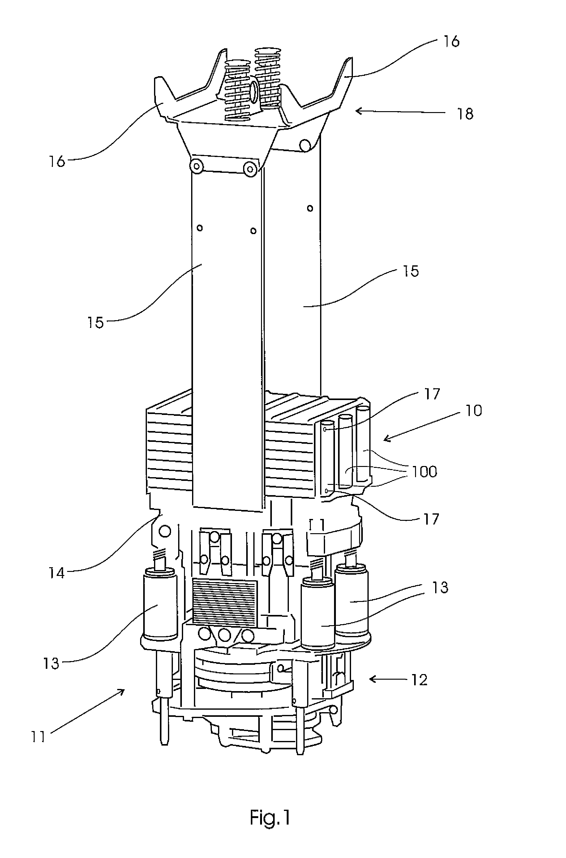
[0055]FIG. 1 shows a resistor 10 according to the invention mounted in a tap changer for three phases. The resistor 10 shown in the figure comprises three resistor modules 100, one for each phase. The details of the tap changer will not be described in detail here, but it may be mentioned that it comprises, inter alia, a mechanical drive mechanism 12 with a mechanical energy-storage system that drives the diverter switch 11 in the tap changer. These units and their function are described in more detail in patent publication WO2006 / 004527 and in PCT patent applications WO SE2006 / 050552 and WO SE2007 / 050187.

[0056]The above units form a unit that is mounted on a frame structure 14, which in turn is integrated with two beams 15, arranged in parallel and made of an electrically insulating material. At their upper parts the beams are connected to lifting means 16. During mounting, the entire unit is lowered down into a tap changer housing (not shown here), which is filled with transformer...


PUM


Abstract

A resistor for electric high-voltage apparatus, especially for connection to a diverter switch in an on-load tap changer for a high-voltage transformer. The diverter switch and the resistor are arranged in a housing with transformer oil. The resistor includes a number of resistor elements, wherein each resistor element includes a resistive element, arranged in a frame, which are electrically interconnected by a connection member. The frames are designed to enclose resistive elements that include spring elements formed from spirally wound resistance wire. Connection members include a connection plug. A method of mounting a resistor for electric high-voltage apparatus.

Description

FIELD OF THE INVENTION[0001]The present invention relates to a resistor for electric high-voltage apparatus, especially for connection to a diverter switch in an on-load tap changer for a high-voltage transformer, wherein the diverter switch and the resistor are arranged in a housing with transformer oil. In this context, high-voltage apparatus means apparatus for tens of kilovolts, up to for example 800 kV and voltages there above.[0002]The invention also relates to a method of mounting such a resistor.BACKGROUND ART[0003]A diverter switch included in a tap changer is usually used in connection with a transformer to enable tapping at different voltage levels. This occurs in cooperation with a selector connected to the diverter switch. When the power output from a transformer is to be changed from one voltage level to another, this occurs by first connecting the selector to that tapping point of the transformer winding which corresponds to the new voltage level while the diverter sw...

Claims


Application Information

Patent Timeline
Patent Type & Authority Applications(United States)
IPC IPC(8): H01C1/02
CPCH01C1/01H01F29/04H01C13/02H01C3/14
Inventor NILSSON, PETTERSUNDQVIST, DAVIDLUNN, LENA
Owner ABB TECH AG
Why Eureka
Try Eureka