Surface inspection apparatus

a technology for inspection apparatus and surface, applied in the direction of measurement devices, material analysis, instruments, etc., can solve the problems of reducing inspection capability, difficult to maintain uniformity, and difficulty in increasing productivity, and achieve the effect of high accuracy and quick and easy detection of defects

Active Publication Date: 2010-04-15
TOYOTA JIDOSHA KK
View PDF29 Cites 75 Cited by
  • Summary
  • Abstract
  • Description
  • Claims
  • Application Information

AI Technical Summary

Benefits of technology

[0028]The present invention provides a surface inspection apparatus for quickly ...

Problems solved by technology

The above-mentioned visual inspection conducted by a worker imposes a great physical burden on the worker, and it is thus difficult for the worker to continue the inspecting operation for a long time, which makes it difficult to increase the productivity.
Also, the visual inspection depends largely on the ability or efficiency of the worker, and the inspection quality varies to a great extent from one worker to another, which makes it difficult to maintain uniform quality.
In the case of the inspection using the diffusion-type flat lighting as mentioned above at 1), if the area of the surface illuminated is increased, the light diffracts in all directions at minute protrusions or recesses, such as blisters on a painted surface, and the protrusions or recesses do not appear as feature points, resulting in reduced inspection capability.
Thus, as in the case 1) above, the inspection of a surface having a large area, such as that of an automobile body, cannot be completed within a tact time of the conveyor.
Also, metallic powder or mica contained in a coating may be erroneously detected as defects, depending on the orientation of the metallic powder or mica.
However, there is a problem in the detection accuracy at boundaries between light and dark portions of the pattern.
However, the same number of image processing boards, personal computers, lenses, and other devices as that of the cameras is required, resul...

Method used


Image

  • Surface inspection apparatus
  • Surface inspection apparatus
  • Surface inspection apparatus

Examples


first embodiment

[0082]the invention will be described with reference to the drawings.

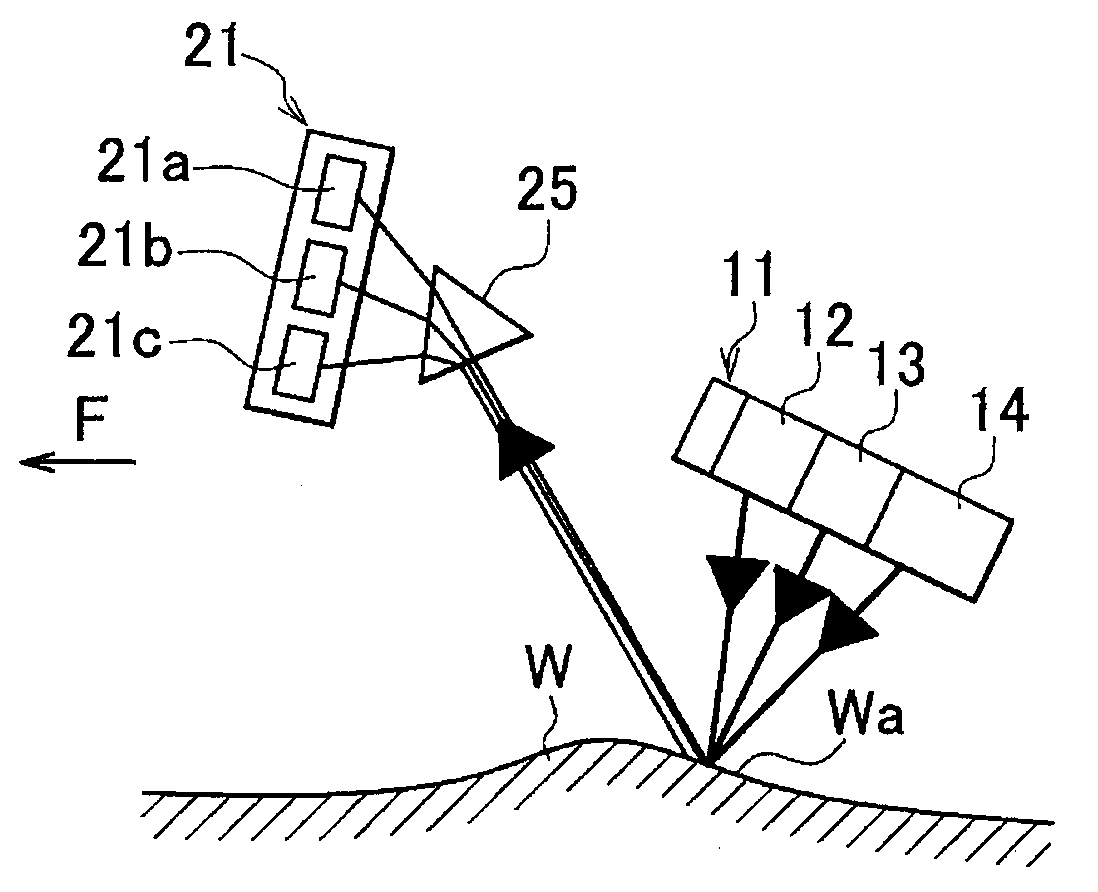
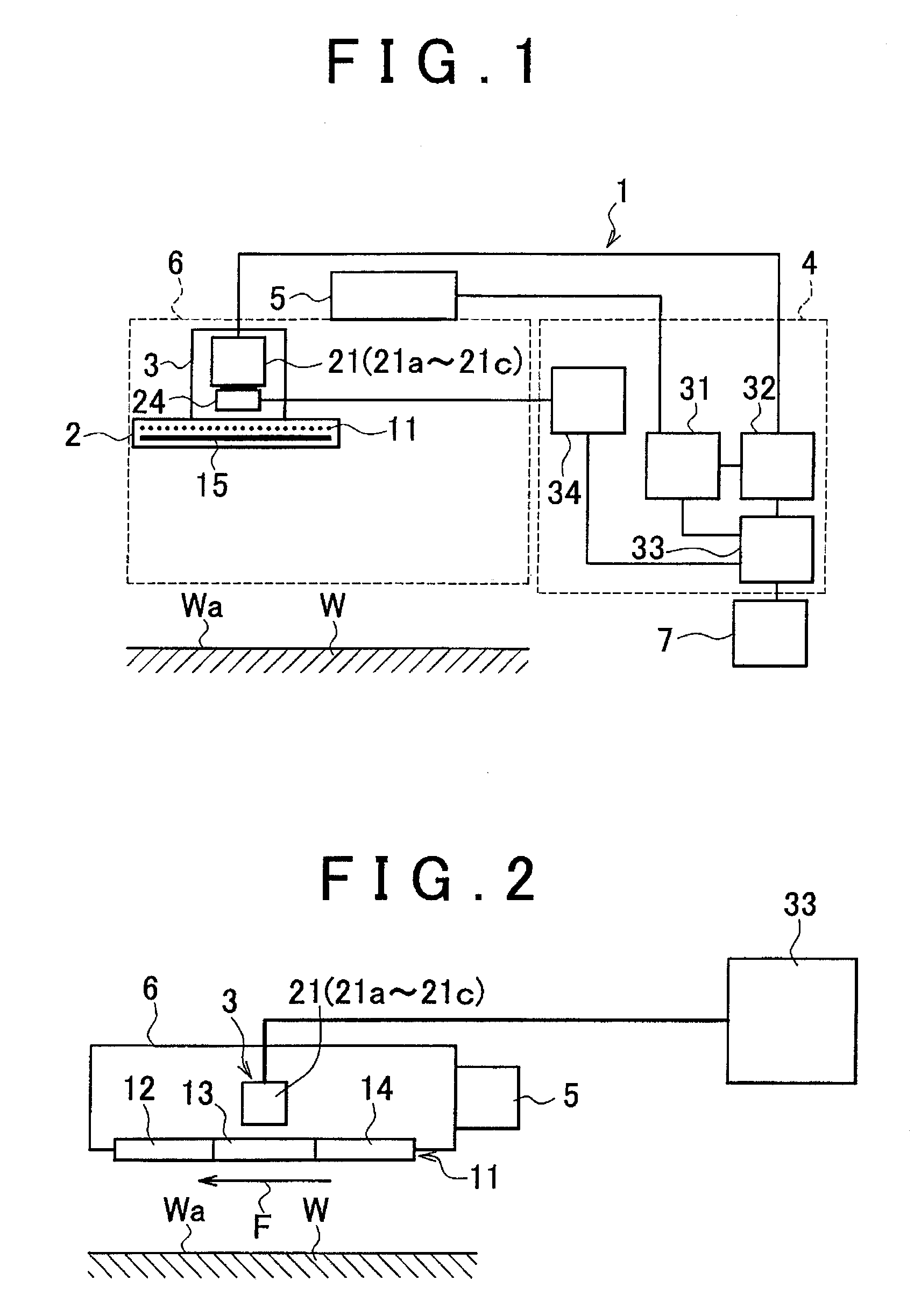
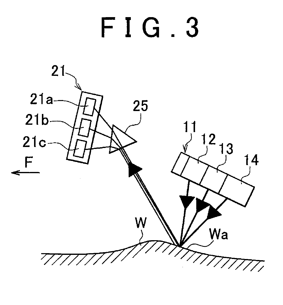
[0083]FIG. 1 is a block diagram illustrating the overall construction of a surface inspection apparatus 1 according to the first embodiment of the invention, and FIG. 2 is a conceptual view useful for explaining the construction of a sensor unit 6, while FIG. 3 is a view schematically showing a method of inspecting a surface state or profile by means of the surface inspection apparatus 1. The surface inspection apparatus 1 of this embodiment is characterized in that the acceptable ranges of inclinations of a line camera 21 and an illuminating device 11 with respect to an inspection surface Wa of a body W to be inspected are large.

[0084]As shown in FIG. 1, the surface inspection apparatus 1 has an irradiating unit 2 that emits a plurality of illumination light beams R, B having mutually different wavelength ranges, an imaging unit 3 that captures images of an inspection surface Wa of a body W to be inspected which i...

second embodiment

[0130]In the second embodiment, on the other hand, an intermediate light source 16 having both of the wavelength ranges of the light sources 12, 13 is provided between the adjacent light sources 12, 13, and an intermediate light source 17 having both of the wavelength ranges of the light sources 13, 14 is provided between the adjacent light sources 13, 14, as shown in FIG. 10A.

[0131]With this arrangement, even when the sensor unit 6 is brought into the above-described inclined position relative to the inspection surface Wa, reflected light having a stable wavelength range can be received by the imaging unit 3, and the accuracy in detection of defects Wb will not be reduced.

[0132]FIG. 11 and FIG. 12 show specific examples that implement the second embodiment. The example shown in FIG. 11 utilizes the arrangement of LED emitters 12a, 13a, 14a used as illuminators of the illuminating means 101. The red light source 12 is formed by placing a plurality of red LEDs 12a in a line, and the ...

third embodiment

[0143]Next, the invention will be described with reference to FIG. 13 through FIG. 24. In these figures, the same reference numerals as used in the above-described embodiments are used for identifying the same or corresponding constituent elements, of which no detailed description will be provided.

[0144]In this embodiment, an object detected by the image processing means 33 is identified. More specifically, it is determined whether the object detected by the image processing means 33 is a protrusion / recess defect Wb, a color defect Wc1, Wc2, a foreign matter Wd, such as dust deposited on the inspection surface Wa, or a design feature, such as a hole We formed through the inspection surface Wa, step, or an edge.

[0145]The color defect means a point, or the like, which is formed on the inspection surface Wa having a single color or substantially the same color and has a color different from that of the inspection surface Wa. The color defect may be a dark-color defect Wc1 that is a dot...


PUM


Abstract

A surface inspection apparatus includes an irradiating unit that has a plurality of light sources that respectively emit a plurality of illumination light beams having different wavelength ranges, and irradiates an inspection surface as a surface of a body to be inspected with the illumination light beams, in a condition where the light sources are located adjacent to each other and arranged in a given order along the inspection surface, an imaging unit that images reflected light when the illumination light beams are reflected by the inspection surface, so as to obtain a plurality of items of image data corresponding to the respective wavelength ranges, and a control unit that detects a detection object on the inspection surface, based on the items of image data corresponding to the respective wavelength ranges which are obtained by the imaging unit.

Description

INCORPORATION BY REFERENCE[0001]The disclosures of Japanese Patent Application No. 2008-264308 filed on Oct. 10, 2008 and Japanese Patent Application No. 2009-087972 filed on Mar. 31, 2009 including the specifications, drawings and abstracts are incorporated herein by reference in their entirety.BACKGROUND OF THE INVENTION[0002]1. Field of the Invention[0003]The invention relates to a surface inspection apparatus for determining whether defects, such as minute protrusions or recesses, are present on a flat, smooth surface, such as a surface of an automobile body coated with a paint film.[0004]2. Description of the Related Art[0005]On production lines of automobile factories, for example, an inspecting operation to check if defects, such as minute protrusions or recesses, are present on a paint film surface of an automobile body is conducted through direct, visual inspection of the paint film surface by a worker.[0006]Also, four methods, namely, 1) inspection using diffusion-type fla...

Claims


Application Information

Patent Timeline
IPC IPC(8): G01N21/00
CPCG01N21/255G01N21/55G01N2021/8854G01N2021/8845G01N21/8806
Inventor ASADA, YASUNORIMIYAZATO, NORIOYAMAZAKI, EIJI
Owner TOYOTA JIDOSHA KK
Why Eureka
Try Eureka