Loudspeaker device

a technology of loudspeaker and support system, which is applied in the direction of frequency response correction, electrical transducers, instruments, etc., can solve the problems of non-linear distortion, aging, and the inability of the actual loudspeaker to perform faithful conversion, and achieve stable distortion removal processing, and high feasibility

Active Publication Date: 2010-04-15
PANASONIC CORP
View PDF20 Cites 151 Cited by
  • Summary
  • Abstract
  • Description
  • Claims
  • Application Information

AI Technical Summary

Benefits of technology

[0034]According to the first aspect, most of the non-linear distortion can be removed by the feedforward processing based on the preset filter coefficient. Further, robust distortion removal with respect to, for example, the secular change of the stiffness of the support system of the loudspeaker, and the like can be performed by the feedback processing. In other words, according to the present aspect, the feedforward processing section performs processing based on the preset filter coefficient, and the feedback processing section performs the above robust distortion removal, thereby providing a loudspeaker device which is capable of performing more stable distortion removal processing with high feasibility, without performing processing of updating the parameter of the loudspeaker. Further, according to the present aspect, the frequency characteristic concerning the vibration of the loudspeaker can be approximated to the predetermined frequency characteristic by the feedback processing.
[0035]According to the second aspect, most of the non-linear distortion can be removed by the feedforward processing based on the preset filter coefficient, and the robust distortion removal with respect to, for example, the secular change of the stiffness of the support system of the loudspeaker, and the like can be performed by the feedback processing based on the error signal. Thus, a loudspeaker device can be pr

Problems solved by technology

However, it is hard for an actual loudspeaker to perform faithful conversion due to limitations on its structure.
Due to these reasons, the amplitude of the loudspeaker is not necessarily proportional to the magnitude of the inputted electric signal, and there is a problem that non-linear distortion occurs.
However, especially, the s

Method used


Image

  • Loudspeaker device
  • Loudspeaker device
  • Loudspeaker device

Examples


first embodiment

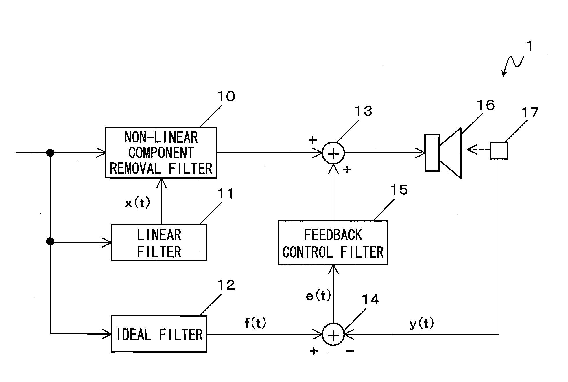
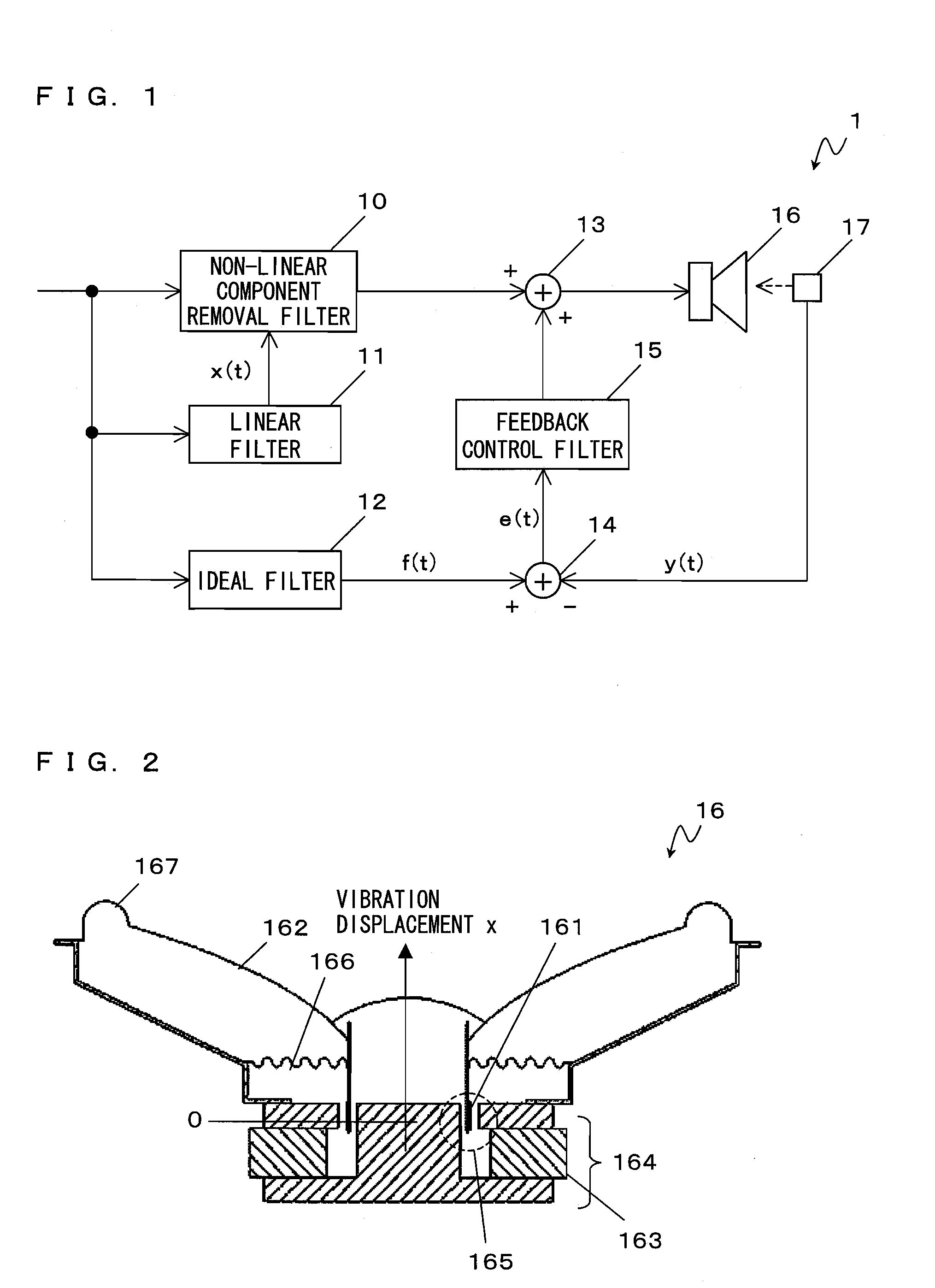
[0098]With reference to FIG. 1, a loudspeaker device 1 according to a first embodiment of the present invention will be described. FIG. 1 is a block diagram showing an exemplary configuration of the loudspeaker device 1 according to the first embodiment. As shown in FIG. 1, the loudspeaker device 1 comprises a non-linear component removal filter 10, a linear filter 11, an ideal filter 12, adders 13 and 14, a feedback control filter 15, a loudspeaker 16, and a sensor 17.

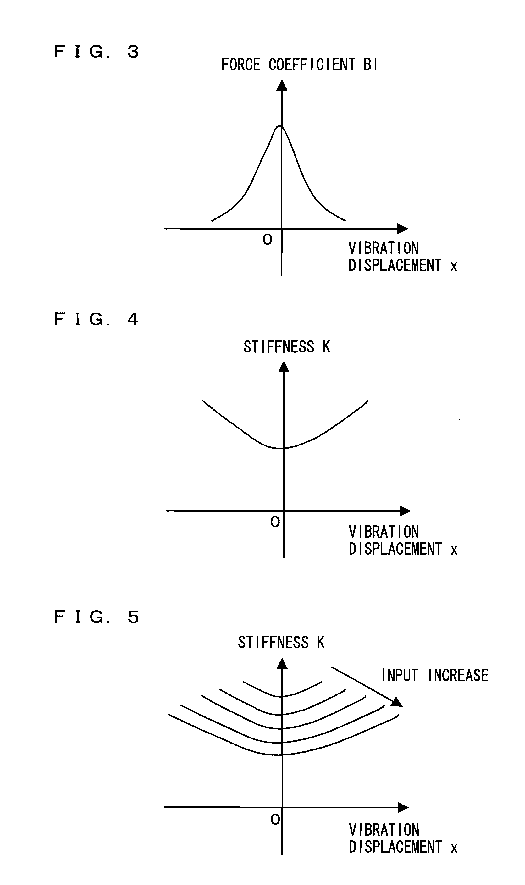
[0099]Here, with reference to FIG. 2, the cause of occurrence of non-linear distortion in the loudspeaker 16 will be described. FIG. 2 is a cross-sectional view of the common loudspeaker 16. As shown in FIG. 2, the loudspeaker 16 comprises a voice coil 161, a diaphragm 162, a magnet 163, a magnetic circuit 164, a damper 166, and an edge 167. The magnetic gap 165 is formed in the magnetic circuit 164 shown in FIG. 2. According to the Fleming's left-hand rule with a magnetic flux density B in the magnetic gap 165 and a ...

second embodiment

[0128]With reference to FIG. 8, a loudspeaker device 2 according to a second embodiment of the present invention will be described. FIG. 8 is a block diagram showing an exemplary configuration of the loudspeaker device 2 according to the second embodiment. In FIG. 8, the loudspeaker device 2 comprises a non-linear component removal filter 10, a linear filter 11, an ideal filter 12, an adder 13, an adder 14, a feedback control filter 15, a loudspeaker 16, a sensor 17, and a previous-stage filter 20. As shown in FIG. 8, the loudspeaker device 2 according to the present embodiment differs from the above loudspeaker device 1 shown in FIG. 1 in newly having the previous-stage filter 20. The following will describe mainly the difference. Since the non-linear component removal filter 10, the linear filter 11, the ideal filter 12, the adder 13, the adder 14, the feedback control filter 15, the loudspeaker 16, and the sensor 17 are the same as those described in the first embodiment, the sam...

third embodiment

[0140]With reference to FIG. 11, a loudspeaker device 3 according to a third embodiment of the present invention will be described. FIG. 11 is a block diagram showing an exemplary configuration of the loudspeaker device 3 according to the third embodiment. In FIG. 11, the loudspeaker device 3 comprises a non-linear component removal filter 10, an ideal filter 12, an adder 13, an adder 14, a feedback control filter 15, a loudspeaker 16, a sensor 17, and a previous-stage filter 20. The loudspeaker device 3 according to the present embodiment differs from the loudspeaker devices 1 and 2 shown in FIGS. 1, and 7 to 10 in that the non-linear component removal filter 10 is located between the adder 13 and the loudspeaker 16, and by the difference, the loudspeaker device can widen to a low-frequency band the frequency band in which the effect of distortion removal is obtained.

[0141]The following will describe mainly the above difference with reference to FIG. 11. In FIG. 11, as the loudspea...


PUM


Abstract

The loudspeaker device according to the present invention comprises a loudspeaker; a feedforward processing section for performing feedforward processing on an electric signal to be inputted to the loudspeaker based on a preset filter coefficient so that non-linear distortion which occurs from the loudspeaker is removed; and a feedback processing section for detecting vibration of the loudspeaker, and performing feedback processing on an electric signal concerning the vibration with respect to the electric signal to be inputted to the loudspeaker. The feedback processing section performs feedback processing on the electric signal concerning the vibration so that the non-linear distortion which occurs from the loudspeaker is removed and so that a frequency characteristic concerning the vibration of the loudspeaker becomes a predetermined frequency characteristic.

Description

TECHNICAL FIELD[0001]The present invention relates to a loudspeaker device, and more particularly to a loudspeaker device for removing distortion which occurs from a loudspeaker.BACKGROUND ART[0002]Conventionally, there has been a desire to faithfully convert an electric signal into a sound wave in a normal loudspeaker which does not perform electric signal processing. However, it is hard for an actual loudspeaker to perform faithful conversion due to limitations on its structure. For example, in a magnetic circuit constituting the loudspeaker, because of its structure, a magnetic flux density in a magnetic gap decreases as amplitude increases. Then, a force coefficient also decreases with the decrease of the magnetic flux density. The stiffness of a support system such as a damper, an edge, and the like changes according to the magnitude of the amplitude because of the structure of the support system. Due to these reasons, the amplitude of the loudspeaker is not necessarily proport...

Claims


Application Information

Patent Timeline
IPC IPC(8): G10K11/16H04B15/00
CPCH04R3/08
Inventor KUZE, MITSUKAZU
Owner PANASONIC CORP
Why Eureka
Try Eureka