Chain Tensioning Apparatus with Temperature-Based Leakdown

a technology of tensioning apparatus and chain, which is applied in the direction of mechanical equipment, belts/chains/gearrings, and mechanical components, can solve the problems of reducing the control of the chain drive, causing the tensioner to experience “pump up”, and the assembly stiffness decreases, so as to achieve a faster rate, less viscosity, and the effect of reducing the tension

Inactive Publication Date: 2010-04-15
GM GLOBAL TECH OPERATIONS LLC
View PDF1 Cites 27 Cited by
  • Summary
  • Abstract
  • Description
  • Claims
  • Application Information

AI Technical Summary

Benefits of technology

[0004]An apparatus for tensioning a chain is provided that compensates for the affect of temperature on oil viscosity by providing, in addition to a continuously open oil leakage path, an additional leakage path open only at lower temperatures when oil is more viscous and leaks at a slower rate. The additional leakage path is also referred to as a variable flow passage or

Problems solved by technology

However, as oil temperature is increased, the viscosity of oil in the hydraulic chamber is decreased, and thus more oil leaks out of the leakdown path, decreasing stiffness of the assembly.
When the oil temperature is relatively low, viscosity increases and th

Method used


Image

  • Chain Tensioning Apparatus with Temperature-Based Leakdown
  • Chain Tensioning Apparatus with Temperature-Based Leakdown
  • Chain Tensioning Apparatus with Temperature-Based Leakdown

Examples


Embodiment Construction

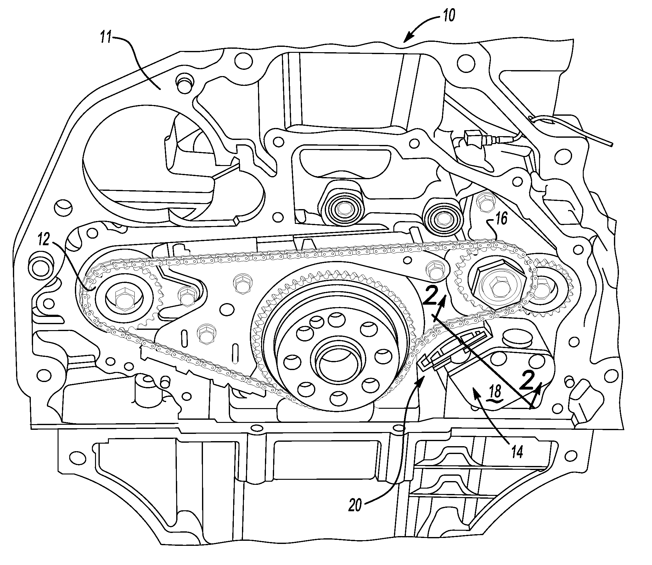
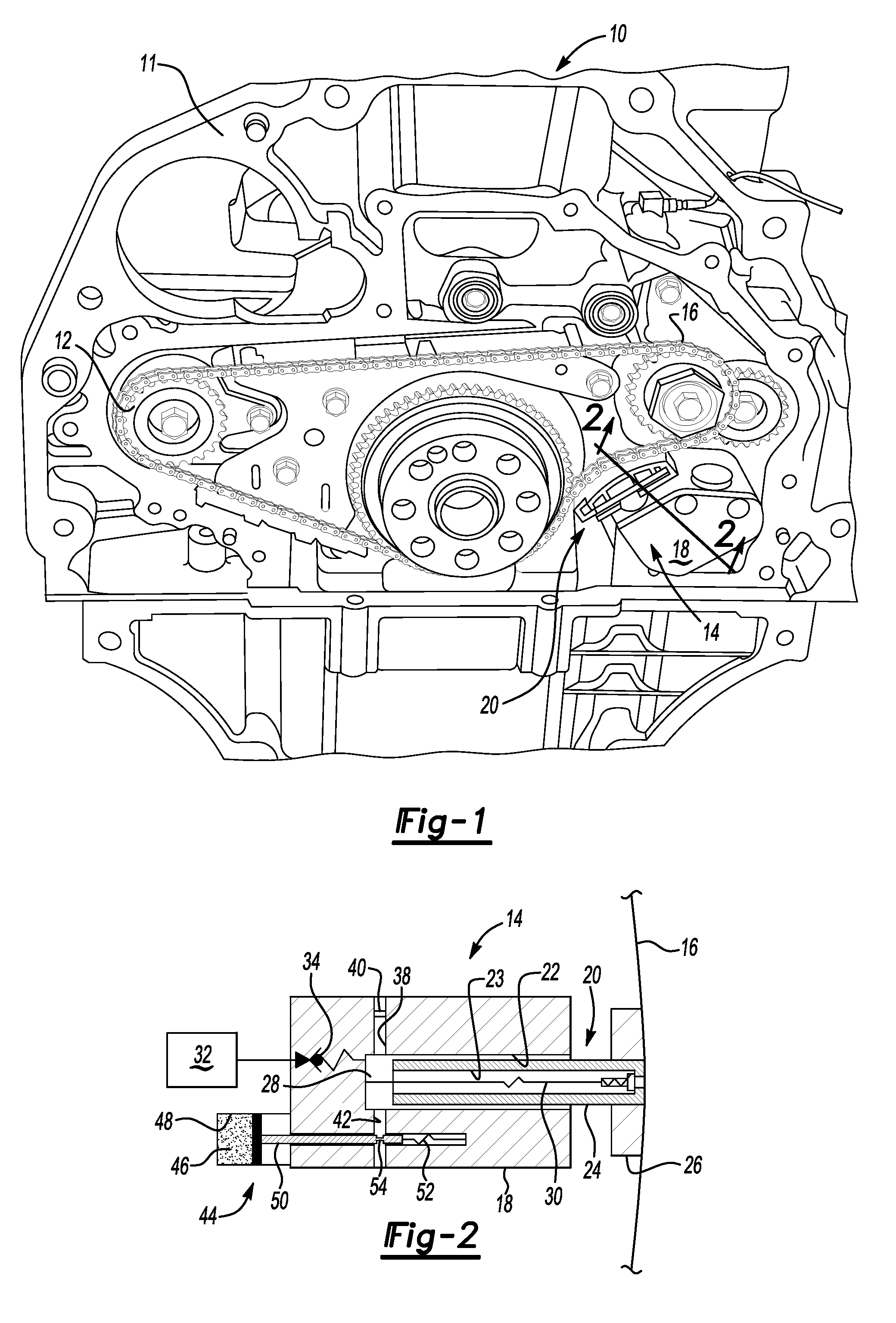
[0014]Referring to the drawings, wherein like reference numbers refer to like components, FIG. 1 is a schematic perspective illustration of an engine assembly 10 that includes an internal combustion engine 11 and a chain driven component, i.e., a balance shaft drive, indicated generally at 12.

[0015]An apparatus referred to as a chain drive tensioner assembly 14 tensions a drive chain 16 of the chain driven balance shaft drive 12. The chain drive tensioner assembly 14 includes a tensioner body 18 and tensioner piston assembly 20 in contact with the drive chain 16.

[0016]It should be appreciated that, while the variable leakdown chain drive tensioner assembly 14 is applied to the chain driven balance shaft drive 12, the variable leakdown chain drive tensioner assembly 14 may alternatively be applied to other chain driven components, which may include but are not limited to, chain drive components used to drive complex valve trains, oil pumps, high pressure fuel injection pumps and wate...


PUM


Abstract

An apparatus for tensioning a chain is provided that compensates for the affect of temperature on oil viscosity by providing, in addition to a continuously open oil leakage path, an additional leakage path open only at lower temperatures when oil is more viscous and leaks at a slower rate. Thus, overall oil leakage at lower temperatures is similar to that at higher temperatures, when the additional leakage path is closed, and the less viscous higher temperature oil leaks at a faster rate from the continuously open oil leakage path. Accordingly, the affect of temperature on hydraulic stiffness of the tensioner assembly is minimized.

Description

TECHNICAL FIELD[0001]The invention relates to an apparatus for tensioning a chain, such as on an automotive engine.BACKGROUND OF THE INVENTION[0002]Chain drive tensioner assemblies are used to operate ancillary components associated with automotive engines. For example, chain drive tensioner assemblies are used to drive complex valve trains, balance shafts, oil pumps, high pressure fuel injection pumps and water pumps.[0003]Known chain drive tensioner assemblies include a chain and a chain drive tensioner system that is operable to create an initial required tension on the chain. Known chain drive tensioner assemblies generally include a tensioner body and a tensioner piston attached to a shoe. Oil pressure within a hydraulic chamber of the tensioner body exerts pressure against the tensioner piston and shoe assembly, which engages the chain to create the required tension. Under impact forces from the chain, some oil leaks from the hydraulic chamber along an oil leakdown path with a...

Claims


Application Information

Patent Timeline
IPC IPC(8): F16H7/12
CPCF16H7/0836F16H2007/0859F16H2007/0812F16H2007/0806
Inventor BULLOCH, CLYDE A.
Owner GM GLOBAL TECH OPERATIONS LLC
Why Eureka
Try Eureka