Method for estimating temperature at a critical point

a critical point and temperature technology, applied in the field of data processing systems, can solve the problems of cost-prohibitive use of a large number of thermal sensors, tighter thermal budgets of these systems, and inability to accurately estimate the temperature at a critical poin

Active Publication Date: 2010-04-15
APPLE INC
View PDF45 Cites 34 Cited by
  • Summary
  • Abstract
  • Description
  • Claims
  • Application Information

AI Technical Summary

Benefits of technology

[0007]At least certain embodiments of the invention disclose methods and apparatuses to estimate temperature at one or more critical points or locations in a data processing system including generating a representation of a thermal model at the one or more critical points, the thermal model using a filtering algorithm to filter at least one temperature sensor at a plurality of frequencies to compensate for time-based under estimation and over estimation in the thermal model. The thermal model can then be stored as one or more equations which can be used at runtime to predict a current and/or future temperature at a critical point on a data processing system. The filtering algorithm (or alternative algorithm) is used to create a model of a transient temperature curve (or other representation) at the one or more critical points. The thermal model can be generated by merging a model of a steady state temperature curve (or other representation) with the thermal model of t

Problems solved by technology

As the operating power consumption of computer systems creeps upwards, the thermal budgets of these systems have become tighter.
It is now a challenge to design a computer system to operate continuously under worst-case thermal loading for extended periods of time, while at the same time both maintaining a desired range of operating performance and maintaining the temperature of the computer housing within safety limits.
As a result, many electronic devices have “hotspots” where there is a potential to overheat and cause injury to the person using the electronic device.
These hotspots are the result of computer systems such as la

Method used


Image

  • Method for estimating temperature at a critical point
  • Method for estimating temperature at a critical point
  • Method for estimating temperature at a critical point

Examples


Embodiment Construction

[0021]Throughout the description, for the purposes of explanation, numerous specific details are set forth in order to provide a thorough understanding of the present invention. It will be apparent, however, to one skilled in the art that the present invention may be practiced without some of these specific details. In other instances, well-known structures and devices are shown in block diagram form to avoid obscuring the underlying principles of embodiments of the present invention.

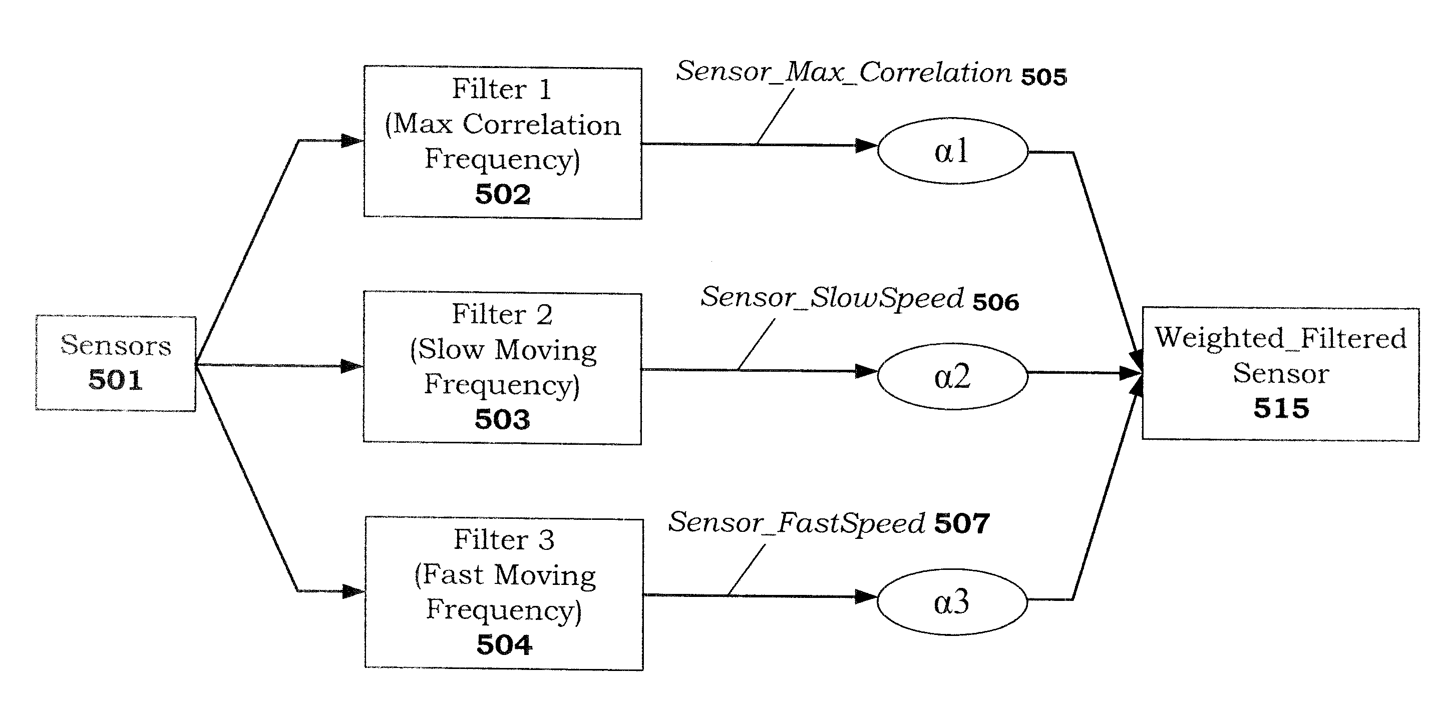
[0022]Methods and apparatuses for estimating temperature at a critical point (e.g., the bottom outside housing of a laptop computer) are described. At least certain embodiments of the invention disclose a method and apparatus to estimate temperature at a critical point in a data processing system including receiving temperature data from temperature sensors, separating the estimation of the steady state temperature curve from the estimation of the transient temperature curve at the critical point, and m...


PUM


Abstract

Methods and apparatuses are disclosed to estimate temperature at one or more critical points in a data processing system comprising modeling a steady state temperature portion of a thermal model at the one or more critical points using regression analysis; modeling the transient temperature portion of the thermal model at the one or more critical points using a filtering algorithm; and generating a thermal model at the one or more critical points by combining the steady state temperature portion of the thermal model with the transient temperature portion of the thermal model. The thermal model may then be used to estimate an instantaneous temperature at the one or more critical points or to predict a future temperature at the one or more critical points.

Description

FIELD OF THE INVENTION[0001]At least certain embodiments of the invention relate generally to data processing systems, and more particularly but not exclusively to the estimation of temperatures in data processing systems.BACKGROUND OF THE INVENTION[0002]Computer systems are designed to be able to continuously operate under varying degrees of thermal loading. As the operating power consumption of computer systems creeps upwards, the thermal budgets of these systems have become tighter. It is now a challenge to design a computer system to operate continuously under worst-case thermal loading for extended periods of time, while at the same time both maintaining a desired range of operating performance and maintaining the temperature of the computer housing within safety limits.[0003]Further, computer systems are being packed into smaller profile housing to improve portability. As a result, many electronic devices have “hotspots” where there is a potential to overheat and cause injury ...

Claims


Application Information

Patent Timeline
IPC IPC(8): G06F15/00G01K13/00
CPCG01K7/42G06F1/206G01K7/425G01K1/20G01K7/427G06F1/26
Inventor COX, KEITHKAPOOR, GAURAVARNOLD, VAUGHN
Owner APPLE INC
Why Eureka
Try Eureka