Error correction system for a class-d power stage

Inactive Publication Date: 2010-04-22
BANG & OLUFSEN ICEPOWER
View PDF13 Cites 5 Cited by
  • Summary
  • Abstract
  • Description
  • Claims
  • Application Information

AI Technical Summary

Benefits of technology

[0011]It is an object of the present invention to provide a method and corresponding system by means of which there can be achieved a highly efficient silicon implementation, the ability to accept PDM signals of varying frequency, high PSRR, no phase noise and unlimited regulation region. These and other objects and advantages are attained according to the method and corresponding system according to the present invention.SUMMARY OF THE INVENTION
[0026]filtering the error signal by a low pass filter for reducing the higher harmonics of the carrier;
[0028]feeding the compensator output to a zero cross detector or comparator, thus providing a carrier for re-modulation or re-timing by feeding the filtered signal to a zero cross detector or comparator, which controls the output stage.
[0034]means for filtering the error signal by a low pass filter for reducing the higher harmonics of the carrier;
[0037]means for feeding the compensator output to a zero cross detector or comparator, thus providing a carrier for re-modulation or re-timing by feeding the filtered signal to a zero cross detector or comparator, which controls the output stage.
[0039]According to the invention there is provided a fundamentally new control method for improved amplification of a pulse-modulated input signal. The application range is extremely broad in that the invention can be used with any pulse-modulated input, modulated in the analogue or digital domain, and to feed any load, where a pulsed power signal of controllable quality is needed. Ultimately, the principle of the invention may provide perfect reproduction of the pulsed reference signal, such that the output is a product of the input and a constant independent on any disturbances that are introduced during power conversion.

Problems solved by technology

1) ND conversion of error signal and digital error correction, see for instance U.S. Pat. No. 6,373,334, US-2006-034365, US-2006-208794, U.S. Pat. No. 6,504,427. For this class of systems, the ND conversion of the error signal is complicated and delay or phase shift will inherently limit the correcting loop gain. A system of this kind is illustrated in FIG. 1.
2) Edge or ramp correction unit, see for instance US-2005-012546, WO-9844626. A system of this kind is illustrated in FIG. 2. For this class of systems the fundamental problem is that the generation of the ramp introduces noise and complexity. Further, in the case of varying carrier frequency, the error correction gain becomes inversely proportional with the modulation index thus reducing THD (total harmonic distortion) compensation at high modulation index. Another issue is phase noise generation. Since the correcting unit is not adjusting the width of the pulses symmetrically around the natural sampling points of the PWM signal, the result is addition of phase noise when the pulse width is adjusted.

Method used


Image

  • Error correction system for a class-d power stage
  • Error correction system for a class-d power stage
  • Error correction system for a class-d power stage

Examples


Embodiment Construction

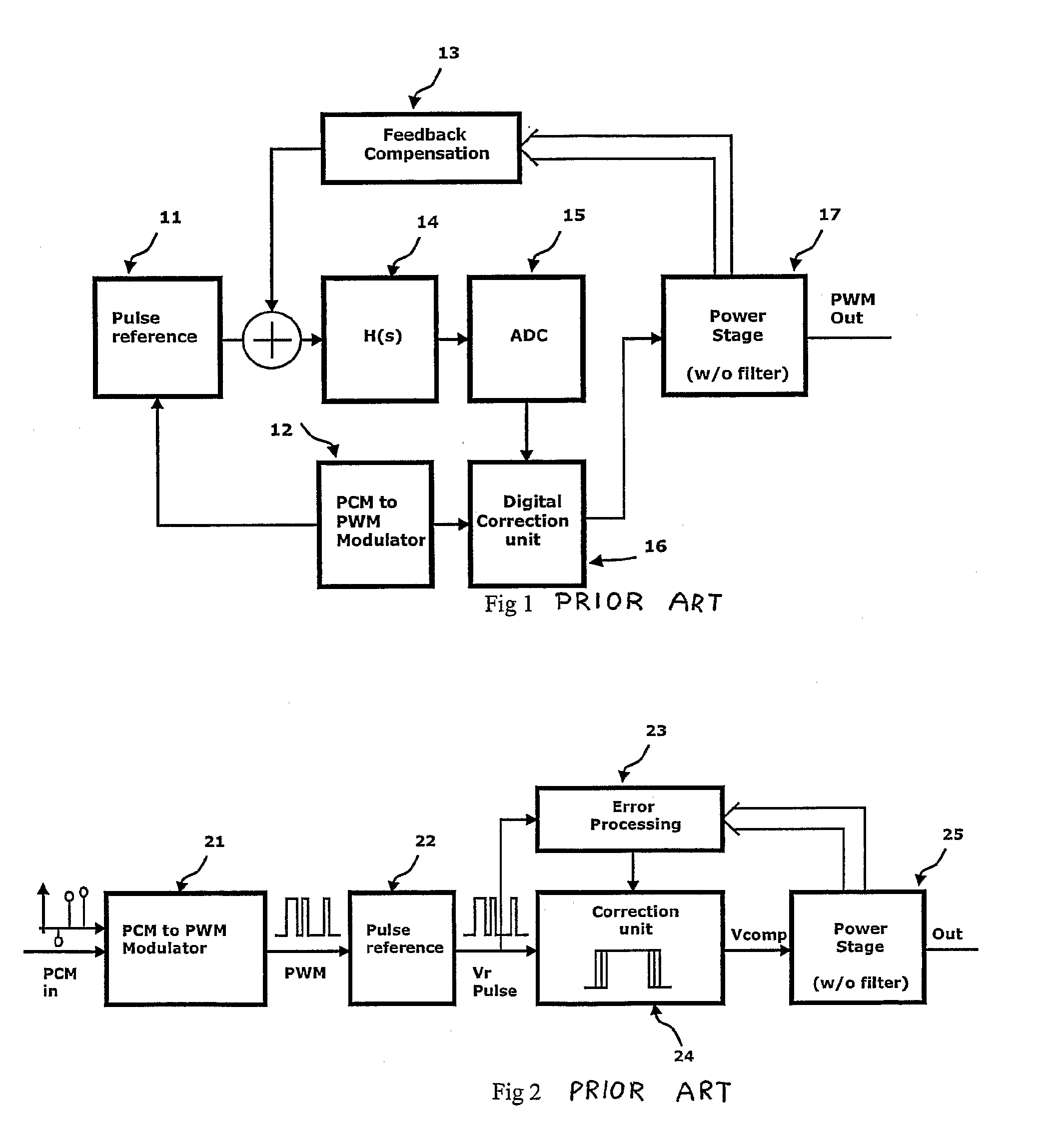
[0050]With reference to FIG. 1 there is shown a block diagram illustrating the principle of a prior art power amplifier with control loop.

[0051]Referring to FIG. 2 there is schematically shown a prior art method of power conversion based on digital pulse modulation;

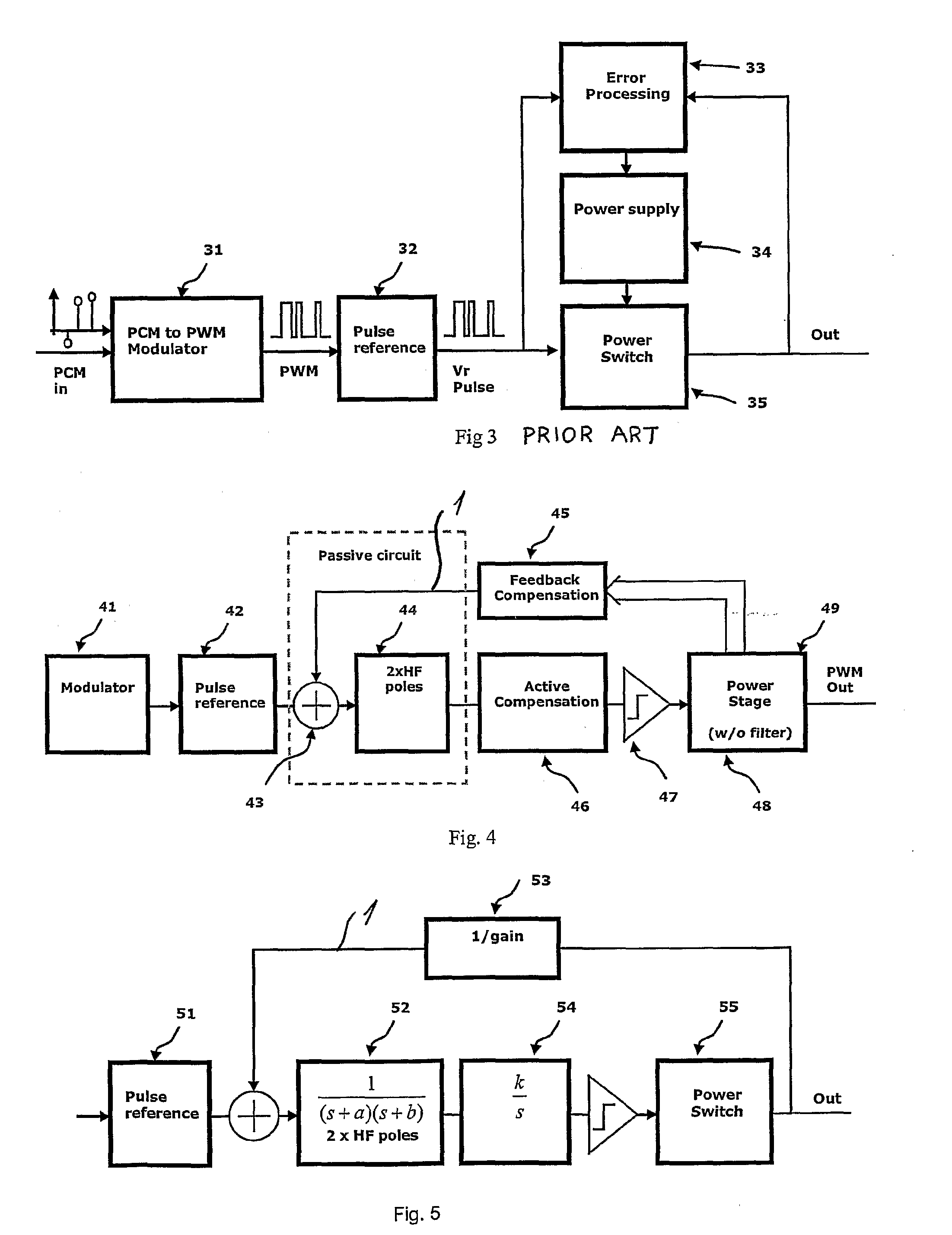
[0052]Referring to FIG. 3 there is shown another example of a prior art circuit.

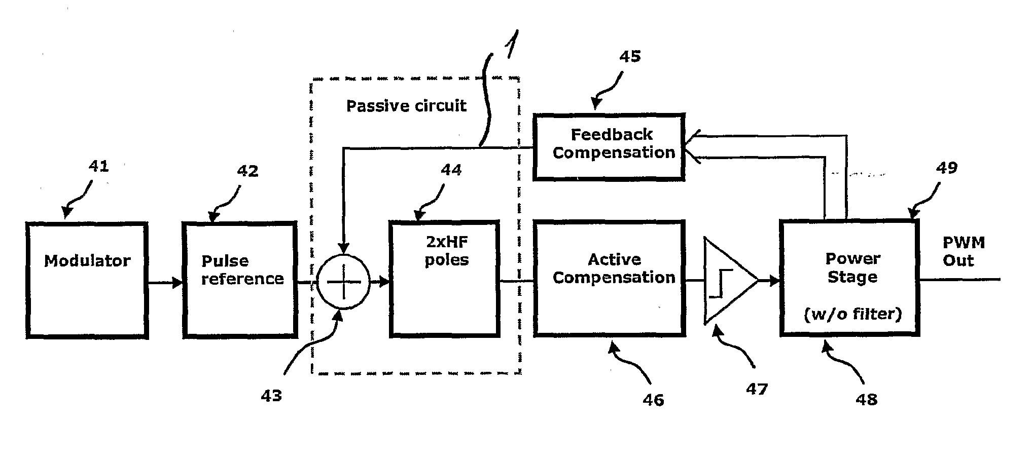
[0053]Referring to FIG. 4 there is shown an embodiment of a system according to the present invention, where a general system using feedback before or after the demodulation filter is shown. First, the PCM is converted to a pulse-coded signal 41. The pulse-coded signal can be of many classes, but for convenience it will be termed PWM here. The next step consists of generating a reference signal 42, where a PWM signal is generated with stabile amplitude. This is often termed as a 1 bit D / A converter. A beneficial method is to invert the output signal since the generation of the error signal is now a summing function 43 instead of a difference f...


PUM


Abstract

The present invention relates to a method for correcting for a source of non-linearity and noise introduced in a switching power amplification stage during power amplification of a pulse-modulated reference signal from a pulse modulator, where the method comprises the following steps: —providing an output stage embedded in an analogue self-oscillating control loop able to receive a pulse-referenced input signal; —generating a feedback signal from the switching power amplification stage or after a demodulation filter; —deriving an error signal by comparing the feedback signal with the reference signal; —filtering the error signal by a low pass filter for reducing the higher harmonics of the carrier; —adding a compensator for generating high loop gain in the audio band; —feeding the compensator output to a zero cross detector or comparator, thus providing a carrier for re-modulation or re-timing by feeding the filtered signal to a zero cross detector or comparator, which controls the output stage. The invention furthermore relates to various systems for implementing the above method.

Description

TECHNICAL FIELD[0001]The present invention relates in general to error correction systems and to power conversion system implementing such an error correction system. More specifically, the invention relates to a pulse-referenced control system for reducing errors introduced by the class D output stage. Application is direct digital audio power conversion and general DC-DC or DC-AC power conversion systems controlled from the digital domain.BACKGROUND OF THE INVENTION[0002]The advantages of power amplification based on a switching power stage are well known. The high efficiency provides several advantages, in terms of minimal weight and volume, higher power handling capability and improved reliability. The fundamental elements in switching power amplification are the modulator, the switching power stage and the demodulation filter to reconstitute the modulated signal. The non-linearity of the switching power stage presents a significant impediment to maintain the modulator performan...

Claims


Application Information

Patent Timeline
IPC IPC(8): H03F3/217H03F1/32
CPCH03F1/32H03F3/217H03F2200/03H03M1/822H03F2200/351H03F2200/372H03M1/1033H03F2200/144G06F21/1073G06F17/00
Inventor NIELSEN, OLE NEIS
Owner BANG & OLUFSEN ICEPOWER
Why Eureka
Try Eureka