Induction power system

Active Publication Date: 2010-04-22
AMIDOF TECH
View PDF10 Cites 34 Cited by
  • Summary
  • Abstract
  • Description
  • Claims
  • Application Information

AI Technical Summary

Benefits of technology

[0013]The present invention further provides a primary side circuit. The primary side circuit comprises at least one main inductor, and is configured to generate a current-induced magnetic field, such that a secondary side circuit adjacent to the main inductor generates an induced AC. At the same time, the primary side circuit comprises an inverter, a matching inductor, and a main capacitor. The inverter, the matching inductor, the main capacitor, and the main inductor match each other, such that the inverter output consists of a discontinuous current. The inverter comprises a plurality of switches and a driver with a fixed switching frequency. Switching occurs when the discontinuous current is zero or when the discontinuous current flows through the inverse diode of the switch, in order to minimize switching loss.
[0014]An effect of the present invention is that the proposed secondary side circuit is able to provide two sets of power at the same time by connecting a plurality of inductors and capacitors in series and in parallel. One set is a load power and provides power needed by the load.

Problems solved by technology

As the control power and the load power are inseparable, a system standby function supplying power only to the control circuit but not the load circuit is usually unable to be provided.
In such systems, when load power is not required at a no load condition, m

Method used


Image

  • Induction power system
  • Induction power system
  • Induction power system

Examples


Embodiment Construction

[0029]The present invention is illustrated below in detail with reference to the embodiments.

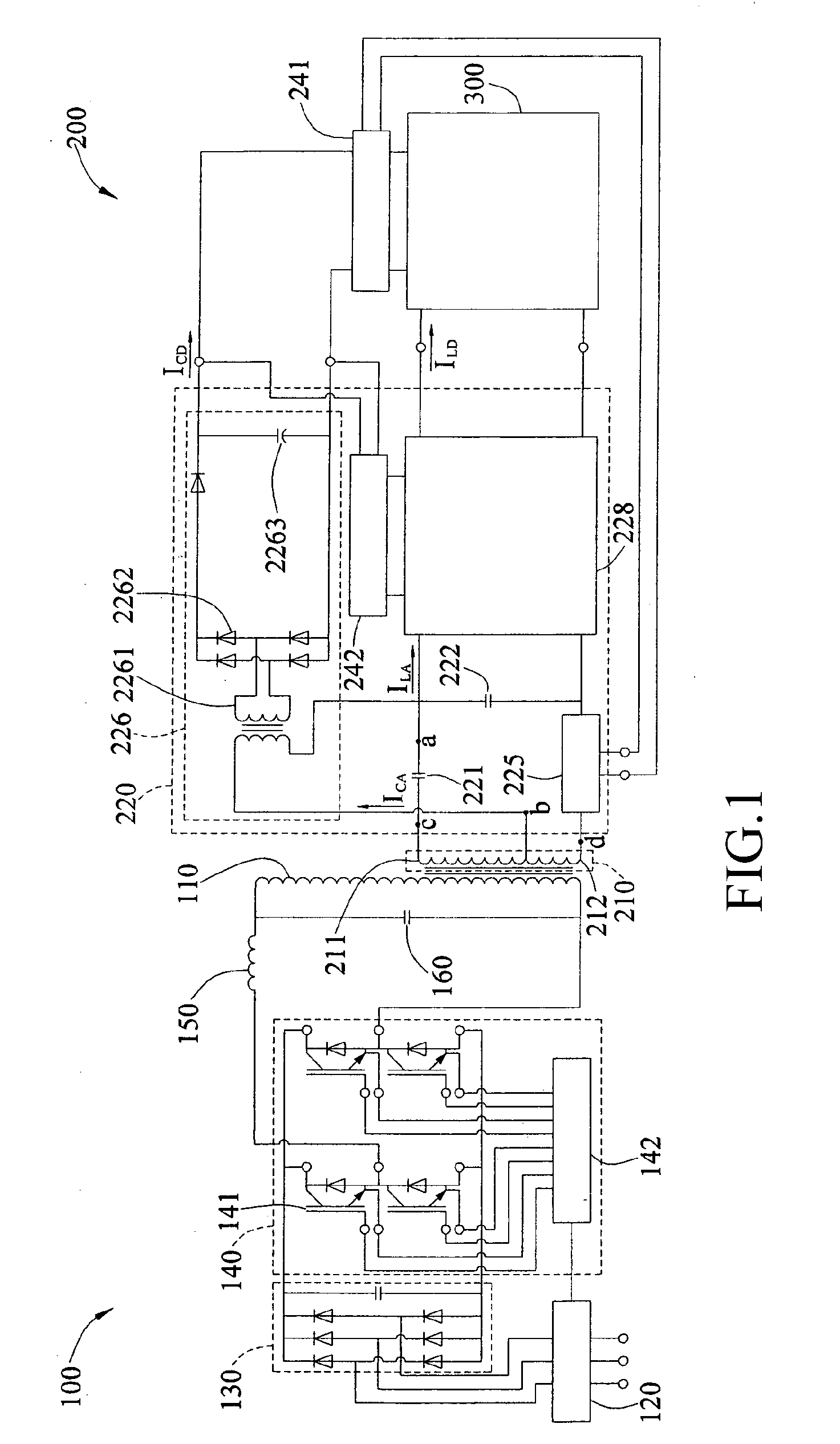
[0030]First, FIG. 1 is an architectural view of an induction power system according to a first embodiment of the present invention. In the first embodiment of the present invention, the induction power system comprises a primary side circuit 100 and a secondary side circuit 200, and is configured to connect and drive a load 300. The primary side circuit 100 at least has a main inductor 110 configured to generate a current-induced magnetic field.

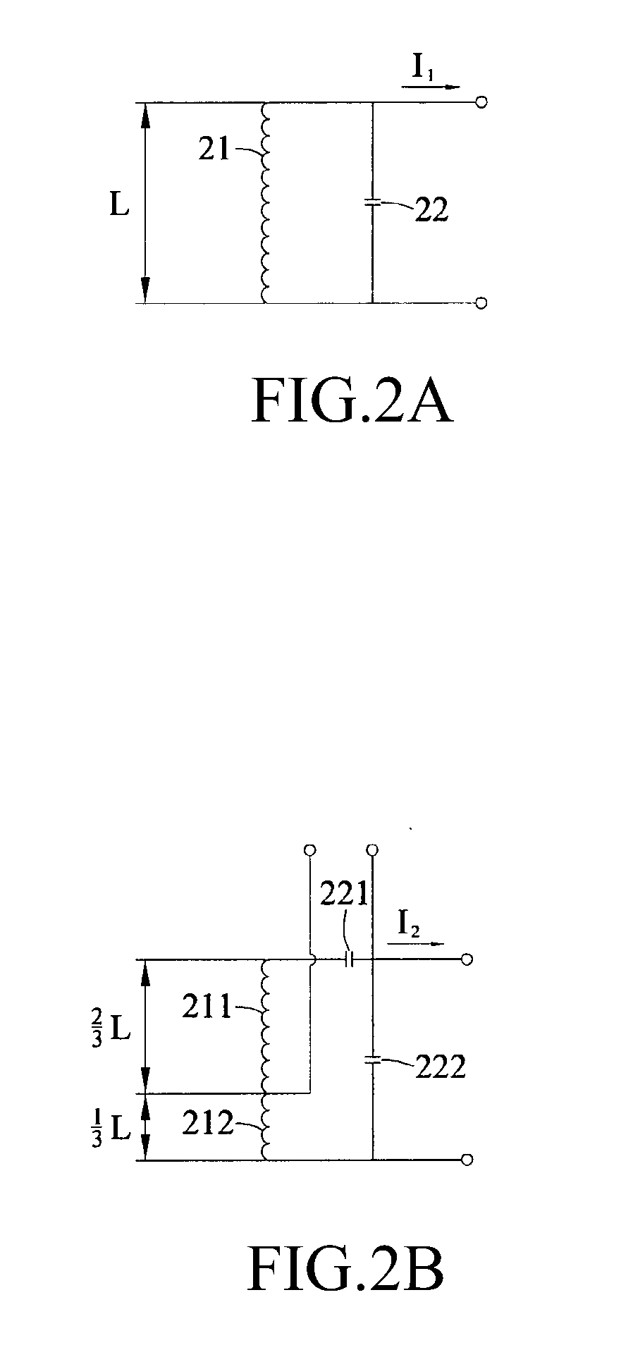
[0031]The secondary side circuit 200 comprises an induction electrification unit 210, a power distribution unit 220, and a first control unit 241. The induction electrification unit 210 is adjacent to the main inductor 110 of the primary side circuit 100, and the induction electrification unit 210 comprises a first inductor 211 and a second inductor 212. The first inductor 211 and the second inductor 212 are electrically connected in series. The first...


PUM


Abstract

An induced power system for being connected with and driving loads (300) includes a primary circuit (100) and a secondary circuit (200). The primary circuit (100) is provided with a primary inductor (110) for generating current induced magnetic filed. The secondary circuit (200) is provided with an induce generation portion (210) and a power distribution portion (220). The induce generation portion (210) is provided with a first inductor (211) and a second inductor (212) connected in series with each other and adjacent with the primary inductor (110), for generating induced alter current. The power distribution portion (220) is provided with a first capacitor (221), a second capacitor (222) and a switching device (225), in which the first capacitor (221) is connected with the first inductor (211) in series to generate series resonance, thus to provide a control power supply. The second capacitor (222) is connected with the first, the second inductors (211, 212) and the first capacitor (221) in parallel to generate parallel resonance, thus to provide a load power supply. When the switching device (225) is on, the load power supply is provided to the loads (300).

Description

BACKGROUND OF THE INVENTION[0001]1. Field[0002]The present invention relates to an induction power system, and more particularly, to an induction power system with high power efficiency.[0003]2. Related Art[0004]An inductively coupled power transfer (ICPT) system is configured to effectively transfer energy of a primary side circuit with a stable power supply into a non-contact secondary side circuit a certain distance away through magnetic field induction. The technology has already been widely used in various applications, for example non-contact battery charging in an electric vehicle, cell phones, portable electronic devices, medical implants, as a non-contact power supply in a material handling device and / or system, and public transportation systems. The technology has advantages such as safety, stability, long service life, and easy maintenance.[0005]In an induction power system, the power supply efficiency is always one factor that needs to be enhanced and surmounted. Previou...

Claims


Application Information

Patent Timeline
IPC IPC(8): H02M7/06H02J17/00
CPCH02M3/33576H02J5/005H02J50/402H02J50/12
Inventor WANG, CHWEISEN
Owner AMIDOF TECH
Why Eureka
Try Eureka