
Motion therapy system

Inactive Publication Date: 2010-04-22
THE BOARD OF TRUSTEES OF THE UNIV OF ILLINOIS
View PDF14 Cites 18 Cited by
  • Summary
  • Abstract
  • Description
  • Claims
  • Application Information

AI Technical Summary

Benefits of technology

[0011]The present invention provides a novel and improved motion therapy system for preventing tissue deterioration occasioned by a lack of body movement. In one embodiment, the system provides a patient with several forms of relief. The motion therapy system includes an inflatable member defining at least one chamber, operatively associated with a body portion to be treated. A connection device is provided for connecting the inflatable member to a control assembly for a pressurized fluid source. The pressurized fluid source, in conjunction with the control assembly, repeatedly inflates and deflates the inflatable member, changing its volume, and in particular, its cross-sectional area. When the inflatable member is positioned between the support surface (e.g., the surface of a bed or chair) and the body portion to be treated, the body portion is moved back and forth or up and down.
[0012]Thus, pressure otherwise applied to the body portion upon contact with the support surface is reduced as closely adjacent body portions are supported by the inflatable member. The use of an inflatable member allows supporting pressure to be gently spread across adjacent portions of the patient's body, and intimate contact over a greater portion of the patient's body is made possible. Further relief is provided by repeatedly inflating and deflating the inflatable member, thus imparting motion to the body portion being treated, as the body portion is moved back and forth between a first position and a second position. The range and rate of motion can be readily varied using conventional equipment already available to medical staff.
[0013]In a second embodiment, the present invention provides enhanced position control with the use of two or more inflatable members. In this embodiment, the invention includes a device for moving and supporting a body portion, comprising a first inflatable member for receiving and surrounding the body portion. The first inflatable member defines at least one first chamber for inflation, so as to securely hold the device around the patient's body portion. A second inflatable member (similar to the inflatable member of the first embodiment above) is operatively associated with the first inflatable member and defines at least one second chamber. A connection device is provided for connecting the first and the second inflatable members to a control assembly for a pressurized fluid source that selectively inflates one or both of the inflatable members. Upon its inflation, the first inflatable member is gently but firmly positioned about the body portion and upon inflation of the second inflatable member, the body portion to be treated is moved by the gentle, controlled rising and falling motion of the second inflatable member. The first inflatable member is preferably connected to the second inflatable member, and thus fixes and maintains the location of the second inflatable member, as the second inflatable member is repeatedly inflated and deflated. If desired, the first inflatable member may be repeatedly inflated and deflated, as well.
[0014]As with the first embodiment, the rate of movement of the body portion being treated may easily be varied using known commercially available equipment. The range of movement is also easily controlled, as the body portion being treated is being moved from a first position to a second position. If desired, the first inflatable member may be arranged so as to enhance blood flow through the body portion. For example, the inflatable member can include a plurality of chambers that are sequentially inflated. As a further alternative, the first inflatable member can include an opening to define an area of the device that does not contact the body portion. This opening could expose a portion of the patient's skin prone to pressure ulcers or the location where a pressure ulcer previously developed.
[0015]As mentioned, the present invention can be readily used in conjunction with conventional equipment already available to medical staff. Accordingly, when the pressurized fluid source selectively inflates the first inflatable member to hold the body portion, selective inflation and deflation can be provided for the second inflatable member to move the body portion back and forth between a first position and a second position. The system provides cushioning and improved support for the body portion being treated. As in other embodiments, the body portion is supported over an enlarged area, using inflatable members that readily conform to the patient's anatomy. Positioning of the applied force is maintained by the first inflatable member, that gently but firmly engages the patient's body.
[0018]Thus, the present invention includes a number of embodiments of devices for moving and supporting a body portion of a patient to reduce the risk of developing pressure ulcers and related devices that both reduce the risk of developing pressure ulcers and deep vein thrombosis.

Problems solved by technology

As is well known, bed-ridden or wheelchair-bound patients who are unable to perform even a modest amount of movement frequently develop decubitus ulcers or pressure sores / ulcers that can result from the development of necrotic tissue.
This can complicate the patient's recovery, and places an added burden on the care giver.
Patients with immobile limbs, such as elderly, debilitated or sedated patients as well as diabetics can suffer significant skin damage due to circulatory deficiency and are particularly prone to pressure ulcers after only a few hours of immobile bed rest.
A continued lack of adequate blood flow, and the resulting lack of oxygen, can lead to cell death and necrosis.
However, the effectiveness of this approach depends on the attentiveness and time constraints of the care giver, and, of course, will vary depending on the situation.
However, an immobile individual can experience inadequate blood flow as a result of inactivity with the inherent risk of venous blood pooling and clot formation.
However, when used on an immobile patient, sequential compression devices do not relieve the pressure applied, for example, to heels and other body parts of the inactive individual.
Moreover, sequential compression devices, when used on a leg, can interfere with other therapeutic treatments such as conventional heel pads.
As a result, significant difficulties are encountered when both deep vein thrombosis and pressure sores must be prevented.

Method used


Image

  • Motion therapy system
  • Motion therapy system
  • Motion therapy system

Examples


Embodiment Construction

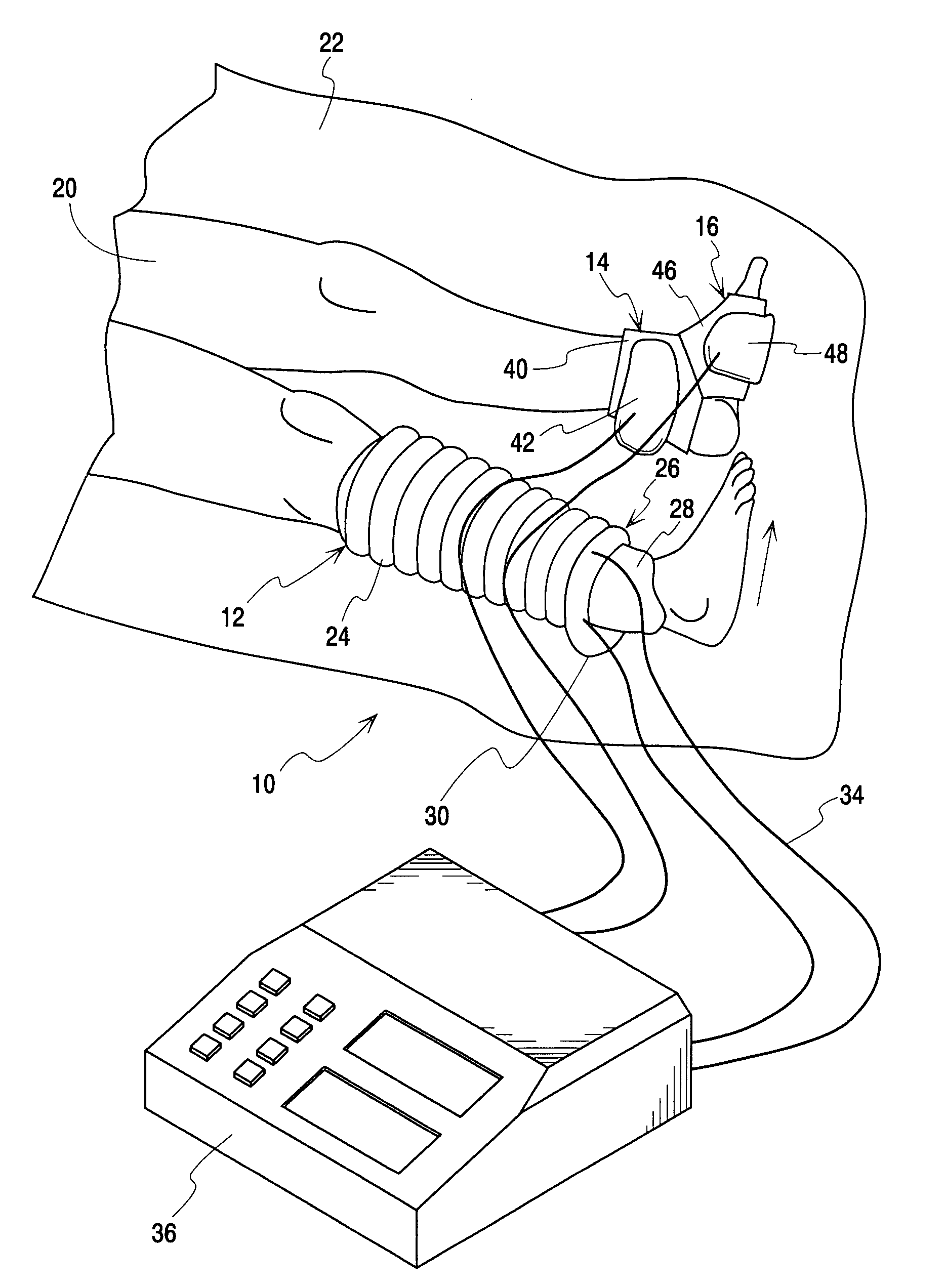
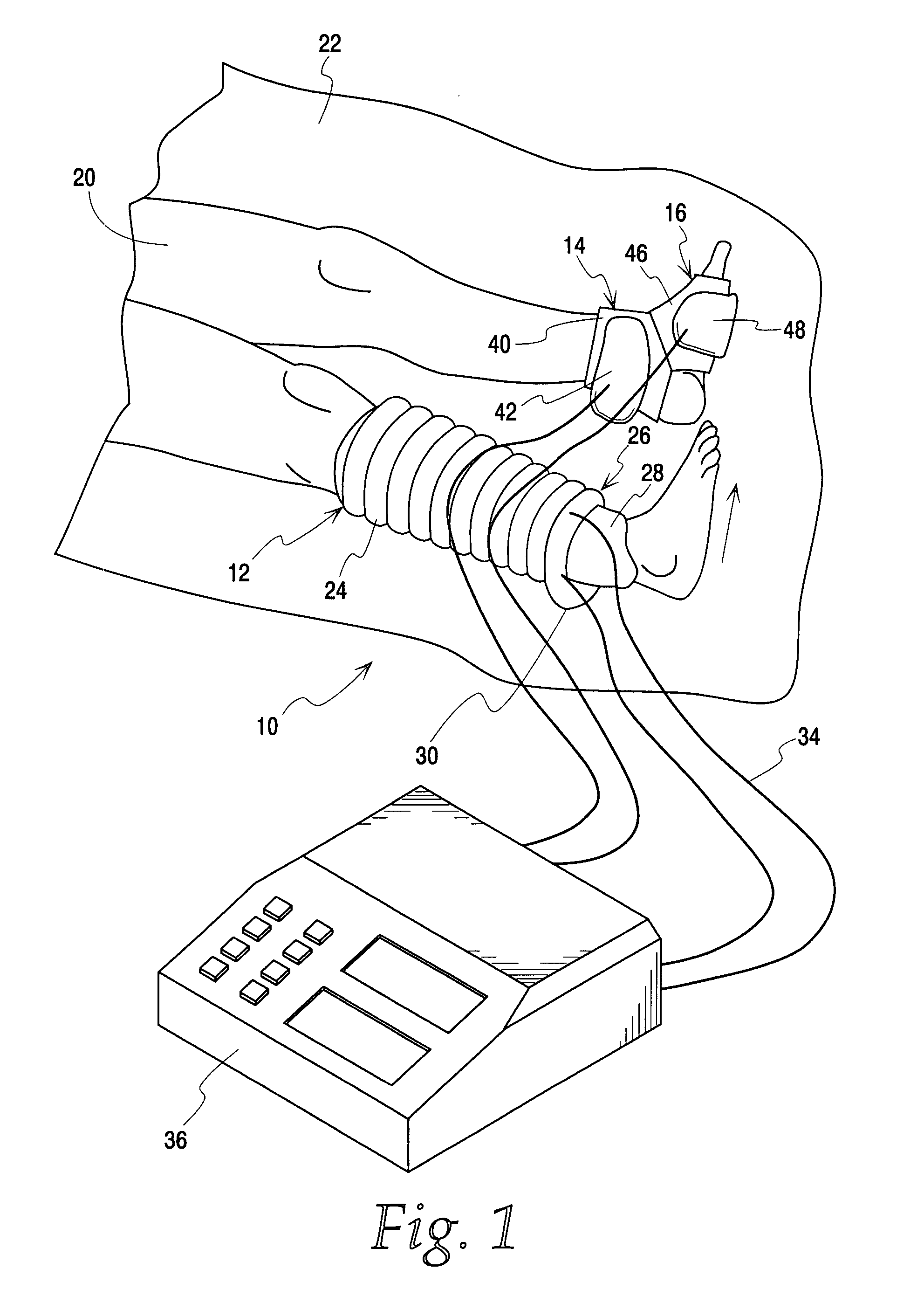
[0030]FIG. 1 illustrates several embodiments of a patient motion therapy system according to the present invention which is generally indicated by the numeral 10. For illustrative purposes, three treatment / therapeutic systems 12, 14 and 16 are shown. Normally, the use of more than one or two treatment systems at one time would not be expected. Each treatment system operates independently to provide movement of a patient's body part that is needed for therapeutic or prophylactic intervention. In particular, the legs 20 of a patient reclining on a bed, table or other support surface 22 are shown. In one embodiment, a first treatment system 12 incorporates two combined systems, a sequential pressurization system 24 and a motion therapy system 26 in a dual purpose device that reduces the risk of deep vein thrombosis and reduces the risk of developing heel pressure ulcers.

[0031]Basically, sequential pressurization system 24 includes a plurality of individual cylindrical pressure cells ar...


PUM


Abstract

Motion therapy systems include an underlying first inflatable member or sleeve which surrounds a patient's body portion, and is at least partially surrounded by an overlying second inflatable member. The first inflatable member provides position control, load dispersion and cushioning for a patient, providing a buffering between the patient and the second inflatable member which is repeatedly inflated and deflated to impart motion to the patient's body portion. The first inflatable member can include a plurality of chambers that are sequentially inflated. The systems may be used, for example, with a patient's upper and lower extremities to minimize the development of pressure ulcers in patients who are relatively immobile and to reduce the risk of blood clot formation.

Description

CROSS-REFERENCE TO RELATED APPLICATION[0001]This application claims the benefit of U.S. Provisional Application for Patent Ser. No. 60 / 851,204, filed on Oct. 12, 2006, which is incorporated herein by reference.FIELD OF THE INVENTION[0002]The present invention relates to a motion therapy system and, in particular, to a device for moving and supporting a body portion of an immobile patient to prevent tissue disorders that can develop due to lack of body movement.BACKGROUND OF THE INVENTION[0003]As is well known, bed-ridden or wheelchair-bound patients who are unable to perform even a modest amount of movement frequently develop decubitus ulcers or pressure sores / ulcers that can result from the development of necrotic tissue. This can complicate the patient's recovery, and places an added burden on the care giver. In extreme cases, surgical debridement and skin grafting of the lesions are required. This condition can affect a wide variety of body portions, especially the torso and uppe...

Claims


Application Information

Patent Timeline
IPC IPC(8): A61H9/00
CPCA61H9/0078A61H2209/00A61H2201/165
Inventor MAGUINA, PIRKO
Owner THE BOARD OF TRUSTEES OF THE UNIV OF ILLINOIS
Features
  • Generate Ideas
  • Intellectual Property
  • Life Sciences
  • Materials
  • Tech Scout
  • Unparalleled Data Quality
  • Higher Quality Content
  • 60% Fewer Hallucinations
Learn More