Lattice dressing

a technology of a cloth dressing and a lining, applied in the field of cloth dressing, can solve the problems of waste generation, and achieve the effects of increasing the mechanical weakening of the material, and increasing the visibility of the wound

Active Publication Date: 2010-04-22
SMITH & NEPHEW INC
View PDF68 Cites 154 Cited by
  • Summary
  • Abstract
  • Description
  • Claims
  • Application Information

AI Technical Summary

Benefits of technology

[0010]The visibility through an opaque material can be increased by the creation of apertures through it. However, the creation of apertures, for example by hole-punching, has the disadvantages of resulting in the generation of waste and also the mechanical weakening of the material. By forming through slits in a material, these slits being capabl

Problems solved by technology

However, the creation of apertures, for example by hole-punching, has the disadvantages o

Method used


Image

  • Lattice dressing
  • Lattice dressing
  • Lattice dressing

Examples


example 1

[0089]To create the wound dressing of example 1, a perforated sheet of polyurethane film was applied to the wound contact surface of a sheet of 4 mm depth polyurethane foam (Allevyn, Smith & Nephew Medical Limited).

[0090]The wound contact surface is that surface which is placed adjacent to or in direct contact with the wound. The non-wound contact surface is that surface which is remote from or opposite the wound contact surface.

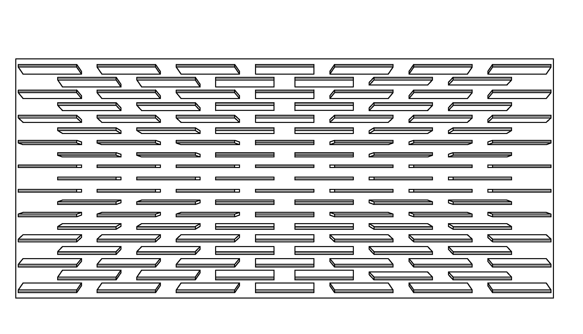
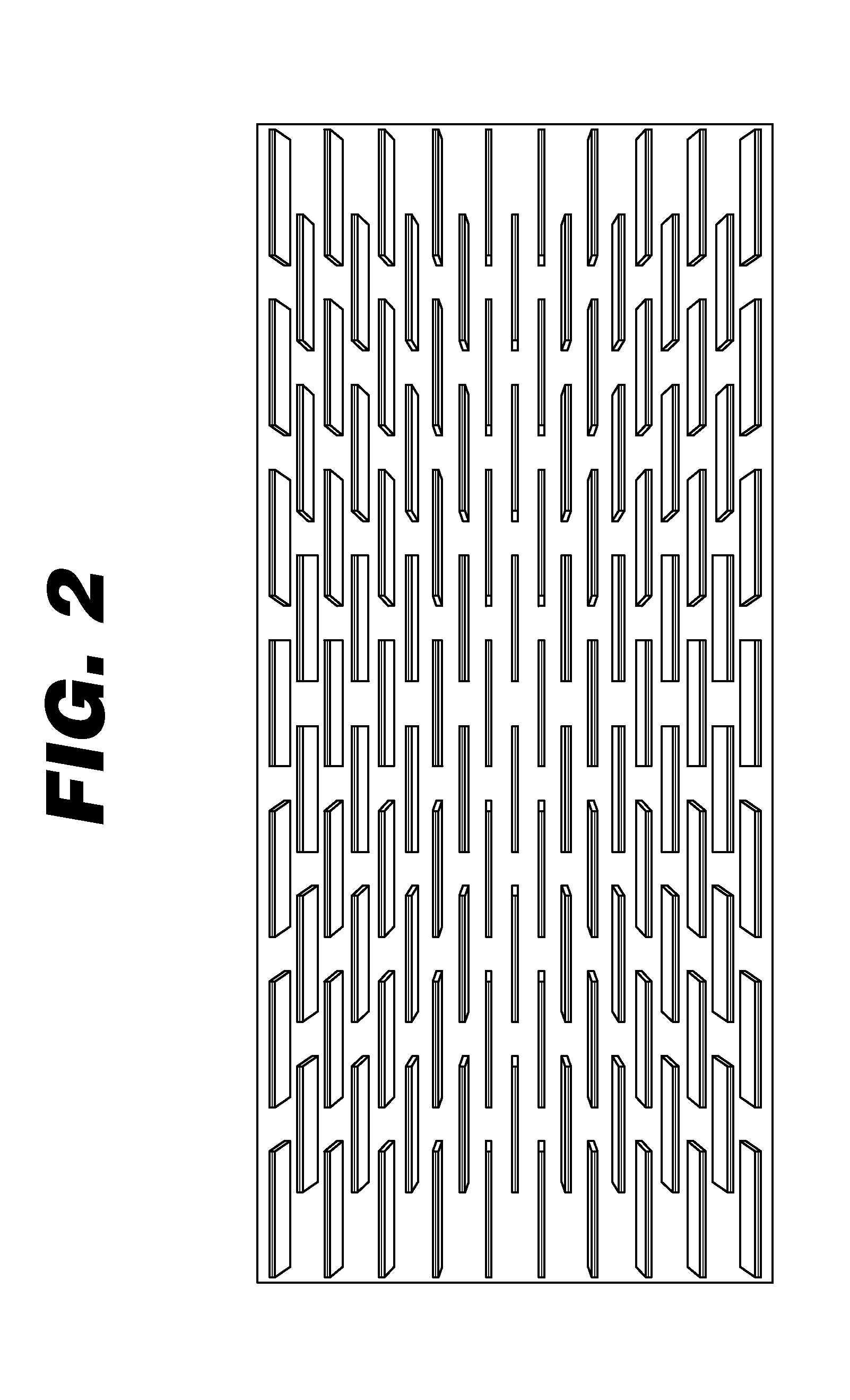
[0091]A cutter of specification shown in FIG. 2 (Cutter blade with 15 mm length blades, linear spacing 5 mm, vertical spacing 5 mm) was used to cut slits in the sheet of polyurethane foam to form a lattice. The cutting action also formed slits in the polyurethane film.

[0092]Following cutting, an extensive force was applied to the lattice in a direction perpendicular to the longitudinal axis of the cuts or slits to produce an open lattice as shown in FIG. 3. A moisture permeable top-film was heat laminated to the non-wound contact layer or surface of the open...

example 2

[0093]To create the wound dressing of example 2, a perforated sheet of adhesive polyurethane film was applied to the wound contact surface of a sheet of 4 mm depth polyurethane foam (Allevyn, Smith & Nephew Medical Limited). The adhesive surface of the film was covered by a siliconised release paper. A cutter of specification shown in FIG. 2 (Cutter blade with 15 mm length blades, linear spacing 5 mm, vertical spacing 5 mm) was used to cut slits in the sheet of polyurethane foam to form a lattice. The cutting action also formed slits in the polyurethane film and siliconised release paper.

[0094]The wound contact surface is that surface which is placed adjacent to or in direct contact with the wound. The non-wound contact surface is that surface which is remote from or opposite the wound contact surface.

[0095]Following cutting, the siliconised release paper was removed and an extensive force was applied to the lattice in a direction perpendicular to the longitudinal axis of the cuts o...

example 3

[0096]To demonstrate the effectiveness of the wound dressing of example 2, the siliconised release paper was removed from the perforated adhesive film and placed, adhesive side down, upon intact skin. The polymeric film release sheet was then removed. A uni-directional contractile force was generated on the skin, upon removal of the polymeric film release sheet, and in a direction perpendicular to the axis of the cuts.


PUM

PropertyMeasurementUnit
Fractionaaaaaaaaaa
Fractionaaaaaaaaaa
Lattice constantaaaaaaaaaa

Abstract

The invention relates to a wound dressing, a method of manufacturing a wound dressing, and in particular to a material for use as and in a wound dressing. A wound dressing can comprise a material movable between an initial conformation and an expanded conformation resulting from applying an extensive force to the material, such that removal of the extensive force can cause a contraction of the material toward a center of a wound. In addition, the wound dressing can comprise a retaining mechanism removably coupled to the material and configured to retain the material in the expanded conformation.

Description

CROSS-REFERENCE TO RELATED APPLICATIONS[0001]This application is a PCT International Application which claims priority to U.S. Patent Application No. 60 / 826,922 filed on 26 Sep. 2006. The disclosure of this prior application is incorporated by reference in its entirety.INTRODUCTION[0002]The present invention relates to a wound dressing, a method of manufacturing a wound dressing, and in particular to a material for use as or in a wound dressing.[0003]Wound dressings are commonly manufactured from sheet materials. These materials include transparent films and adhesives and opaque foams and fibres. These materials generally retain their transparency or opacity upon fluid absorption, the exception being carboxymethylcellulose-based hydrofibre (which is initially opaque and becomes transparent when wet). Wound dressings which rely upon a foam element for exudate management are opaque and require removal and exchange for a new dressing during every wound inspection. This is a disadvantag...

Claims


Application Information

Patent Timeline
IPC IPC(8): A61F13/00A61L15/16B26D3/12
CPCA61B17/083A61B17/085A61F13/00021A61F13/00038A61F13/00995A61F13/0203A61F2013/00859A61F13/069A61F2013/00119A61F2013/00251A61F2013/00548A61F2013/00582A61F2013/0074A61F13/0283Y10T83/04A61F13/02A61B17/08
Inventor GREENER, BRYANFREEDLINE, ALLAN
Owner SMITH & NEPHEW INC
Why Eureka
Try Eureka