
CATALYSTS, SYSTEMS, AND METHODS FOR REDUCING NOx IN AN EXHAUST GAS

a technology of exhaust gas and catalyst, applied in the direction of physical/chemical process catalyst, organic compound/hydride/coordination complex catalyst, etc., can solve the problems of reducing the release of nosub>x /sub>, the use of a reservoir to house ammonia, and the relative high emissions of nosub>x /sub>, so as to reduce nox and reduce nox

Inactive Publication Date: 2010-04-29
CATERPILLAR INC
View PDF24 Cites 52 Cited by
  • Summary
  • Abstract
  • Description
  • Claims
  • Application Information

AI Technical Summary

Benefits of technology

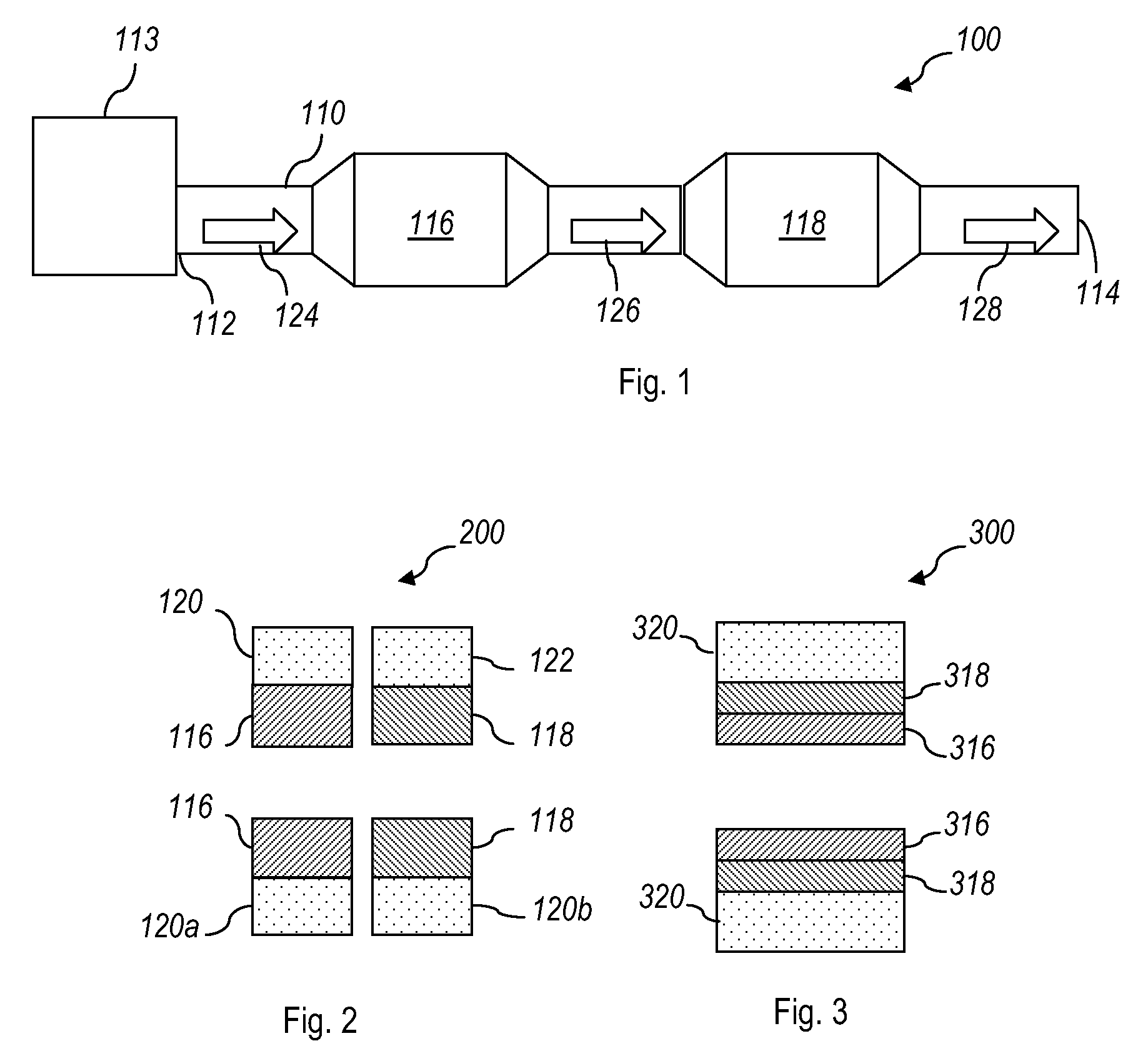
[0014]The catalysts, systems, and methods disclosed herein provide for reduced NOx emissions in the exhaust stream of a lean burning engine. The catalysts include two different types of selective catalytic reduction (SCR) catalysts (i.e., two different types of catalysts that may catalytically reduce NOx using a reductant). The first catalyst is an SCR catalyst having a composition that produces a reductant and the second catalyst is an SCR catalyst having a composition that reduces NOx using the reductant produced by the first SCR catalyst. The second SCR catalyst is associated with the first SCR catalyst such that the reductant produced by the first catalyst may be used by the second SCR catalyst to reduce NOx.

Problems solved by technology

Exhaust from lean burning engines may include relatively high emissions of NOx as compared to combustions engines that operate under fuel rich conditions.
However, the efficient reduction of released NOx by CO requires rich conditions.
One of the potential disadvantages of NH3-SCR technology is the use of a reservoir to house the ammonia source (e.g., urea).
Another potential disadvantage of NH3-SCR technology is the commitment of operators of these machines to replenish the reservoirs with urea as needed and infrastructure for supplying urea to the operators.
Unfortunately, HC-SCR catalyst technology typically does not work with the catalyst used for the NH3-SCR system (e.g., copper zeolite), due to a lack of sufficient catalytic activity.

Method used


Image

  • CATALYSTS, SYSTEMS, AND METHODS FOR REDUCING NOx IN AN EXHAUST GAS
  • CATALYSTS, SYSTEMS, AND METHODS FOR REDUCING NOx IN AN EXHAUST GAS
  • CATALYSTS, SYSTEMS, AND METHODS FOR REDUCING NOx IN AN EXHAUST GAS

Examples


example

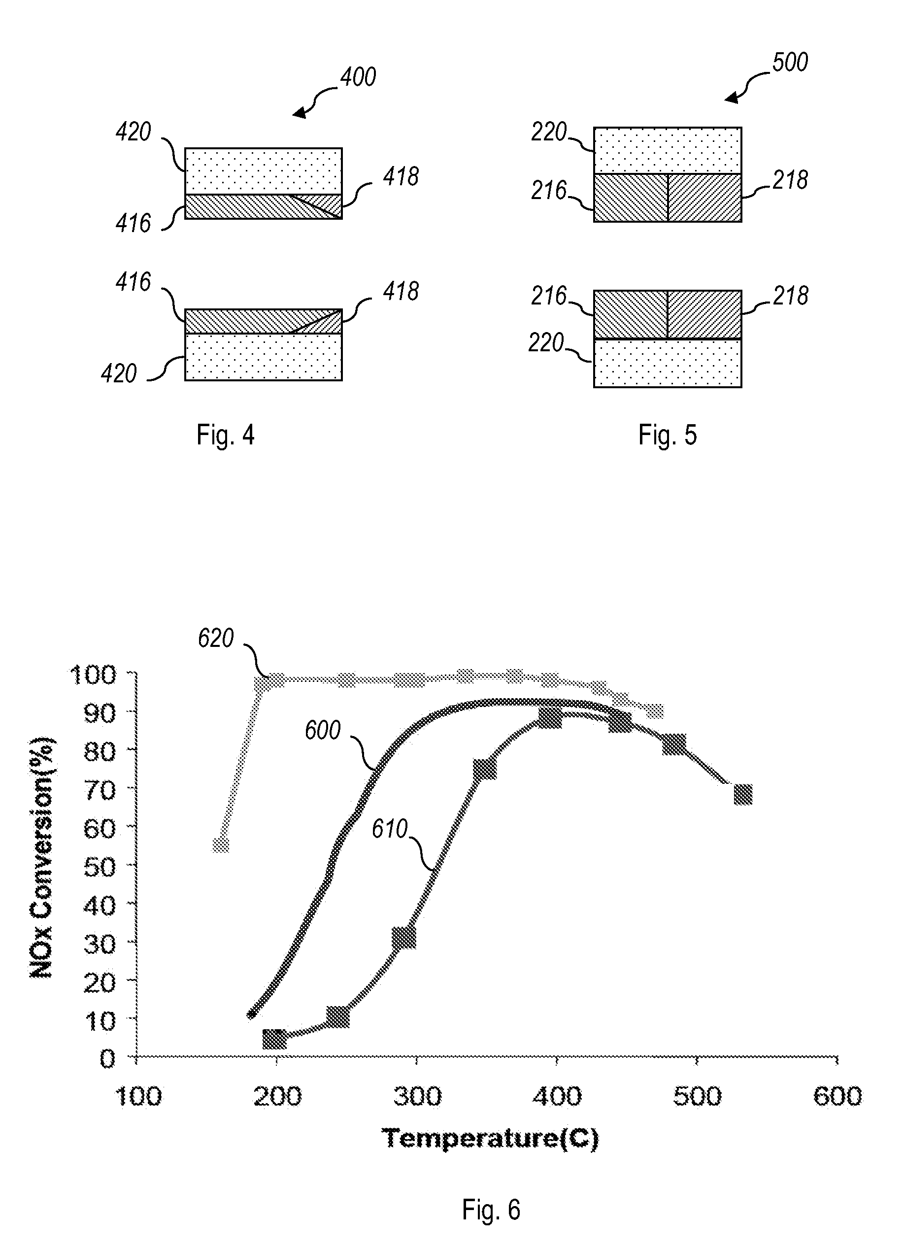
[0058]Example 1 describes an emissions system that includes an HC-SCR catalyst 116 in combination with an NH3-SCR catalyst 118 according to one embodiment. The HC-SCR 116 is positioned upstream from the NH3-SCR 118 in an exhaust system from an internal combustion engine operating on diesel under lean burning conditions. The HC-SCR catalyst 116 may include a silver tungstate supported on a hydroxylated alumina support and having a silver tungstate loading of 2.5 g / in3. The NH3-SCR catalyst 118 may include an iron zeolite with an iron loading of 3.0 g / in3.

[0059]A hydrocarbon reductant is introduced into the exhaust gas stream 124 above the HC-SCR catalyst 116 and acts as a reductant in the conversion of NOx to N2 in the presence of the HC-SCR catalyst 116. Testing is carried out with a space velocity of 60,000 h−1, 10% oxygen in the initial gas stream, and diesel as the hydrocarbon reductant at a C1 to NOx ratio of 10. Catalyst performance is tested using a down ramp method starting a...


PUM

PropertyMeasurementUnit
concentrationaaaaaaaaaa
temperaturesaaaaaaaaaa

Abstract

Catalysts, systems, and methods disclosed herein provide for reduced NOx emissions in the exhaust stream of a lean burning engine. The catalysts include two different types of selective catalytic reduction (SCR) catalysts (i.e., two different types of catalysts that may catalytically reduce NOx using a reductant). The first SCR catalyst (116) is an SCR catalyst having a composition that produces a reductant (e.g., an HC-SCR catalyst that produces ammonia) and the second catalyst (118) is an SCR catalyst (e.g., NH3-SCR) having a composition that reduces NOx using the reductant produced by the first SCR catalyst (116).

Description

TECHNICAL FIELD[0001]The present disclosure relates generally to exhaust emissions systems and catalysts for use in emissions systems of combustion engines.BACKGROUND[0002]The fuel-air mixture used in an engine is selected to achieve desired performance characteristics in the combustion process. Fuel-air mixtures that include excess oxygen are known as “lean” mixtures and are used in lean-burning engines. Alternatively, if the mixture includes a stoichiometric amount or excess amount of fuel, the mixture is rich.[0003]Exhaust from lean burning engines may include relatively high emissions of NOx as compared to combustions engines that operate under fuel rich conditions.[0004]Conversion of the NOx component of exhaust streams to innocuous components generally requires specialized NOx abatement strategies for operation under fuel-lean conditions. Several catalytic systems for reducing NOx in the exhaust of lean burning engines are currently in use and / or under development. Examples of...

Claims


Application Information

Patent Timeline
Patent Type & Authority Applications(United States)
IPC IPC(8): F01N3/10B01J27/24B01J31/12F01N3/00B01J23/50
CPCB01D53/9418F01N13/0093B01D2255/104B01D2255/20738B01D2255/20776B01D2255/50B01D2258/012B01J23/687B01J29/072B01J35/04B01J37/0244B01J37/0246F01N3/2073F01N2510/0684Y02T10/24B01D53/9477Y02T10/12B01J35/56
Inventor CHARBONNEL, SYLVAIN JOSEPHWEI, ZHIYONGDRISCOLL, JAMES JOSHUASILVER, RONALDSTEFANICK, COREY
Owner CATERPILLAR INC
Learn More