Method of fusing optical fibers within a splice package

a technology of optical fibers and splices, applied in the field of splicing and fusing optical fibers, can solve the problems of inability to compensate for small misalignments, small misalignments, and other connection technologies such as mechanical splices or connectors may have higher losses, and achieve the effects of high thermal conductivity, increased mechanical strength, and increased melting poin

Inactive Publication Date: 2010-04-29
GONTHIER FRANCOIS +1
View PDF34 Cites 27 Cited by
  • Summary
  • Abstract
  • Description
  • Claims
  • Application Information

AI Technical Summary

Benefits of technology

[0009]The purpose of this invention is to overcome these drawbacks for permanent mechanical splices. In this invention, the mechanical splice is used to align the fibers, but the fibers are then fused together, rather than leaving them solely supported by the mechanical splice. This is achieved by heating the mechanical splice to a temperature at which the fibers fuse. This can be done easily with low temperature melting point fibers such as plastic fibers, fluoride or chalcogenide glass fiber. For silica fibers, the melting point is most likely above the melting point of the ferrule material, and the heat needs to be delivered to the mechanically aligned fiber ends without adversely affecting the ferrule. In some embodiments, a hole is micro-machined perpendicular to the feed-trough passageway at the position were the fibers joint in the middle of the ferrule. This gives access to fusing the two fiber ends using a local heat source, such as a CO2 laser. The hole must be large enough so that the heat generated during the fiber end fusing process does not damage the ferrule. The mechanical splice can remain in place and thus serve as a splice protection package.
[0010]In some embodiments, the mechanical splice is a ferrule with a passageway with very tight tolerances as to minimize misalignment.
[0014]In some embodiments, the fibers can be fused together by heating the ferrule if the fibers have a lower melting point that the ferrule material and if the ferrule material has a small thermal expansion coefficient, so that that the misalignment at the melting point of the fibers is small.
[0020]In some embodiments, the access hole is large enough such that the heat generated on the fibers and being conducted though the fibers during the fusion process does not damage the ferrule, even if the fibers have a much higher melting point than the ferrule.
[0021]In some embodiments, the ferrule material has a very high thermal conductivity so that the hole can be as small as possible while fusion heat is conducted away into the ferrule without melting the ferrule material.
[0022]In some embodiments, the mechanical splice stays in place after the fusion to act as a splice protection package and to provide additional mechanical strength.

Problems solved by technology

Optical fibers, such as the ones used in telecommunication systems, have very good and well-controlled parameters such as core diameter, ellipticity and eccentricity so that pre-aligned fusion splicers do very good splices, but they cannot compensate for small misalignments occurring during fusion.
The heat of fusion causes some deformation of the fiber ends that can cause such small misalignments.
Other connection technologies such as mechanical splices or connectors may have higher losses but can be disconnected.
Because connectors have to slide in the receptacle, there is always some misalignment because of tolerances, thus higher losses.
As with the connectors, because of the tolerances, the alignment is not a good as using a fusion splicer.
These improved splices however, though the fibers are held in a much tighter manner than previous mechanical splices, still suffer from the fact the fibers have to be secured to the splice to achieve the same pull strength as a good fusion splice.
Furthermore, there can also be a small gap between the fibers that might open due to temperature variations, thus affecting the quality of the connection.
This is an issue for the long-term performance of the splice.

Method used


Image

  • Method of fusing optical fibers within a splice package
  • Method of fusing optical fibers within a splice package
  • Method of fusing optical fibers within a splice package

Examples


Embodiment Construction

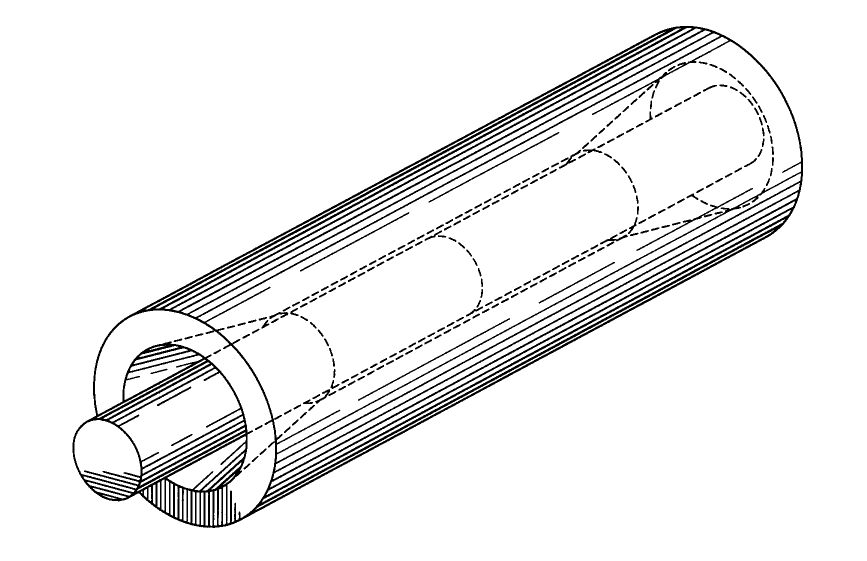
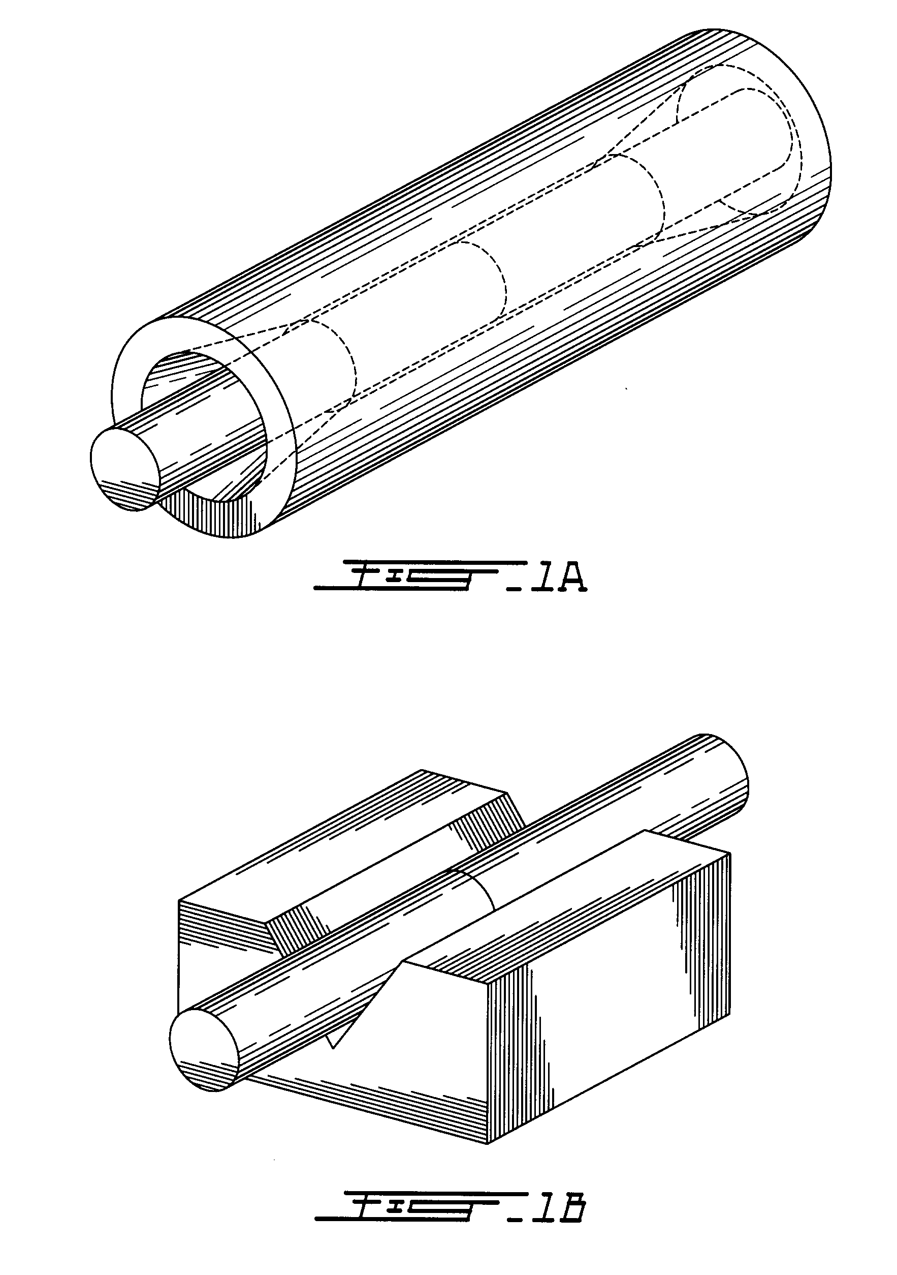
[0031]Mechanical fiber optic splices are ferrules or V-grooves as shown in FIGS. 1a and b respectively. The cylindrical fiber receiving passage in FIG. 1a is shown open and can be closed by mechanical action. The alignment using V-grooves can be very precise, leaving error strictly due to fiber tolerances such as core diameter, cladding diameter, core eccentricity, and core ellipticity. The present quality of the fibers makes it possible to achieve very good transmission (better than 0.1 dB optical loss) by passive alignment in V-grooves. Low cost splicing equipment, i.e. equipment without mechanized alignment, uses V-grooves to prealign the fiber ends before fusion. However, the quality of fusion for those machines is lesser than for the mechanized alignment machine because, not one but two prealigned V-grooves must be used, and they are typically more than 1 cm apart. Thus, there can be misalignment errors. Furthermore, the fibers must be held in the V-grooves with mechanical clam...


PUM

PropertyMeasurementUnit
diameteraaaaaaaaaa
melting pointaaaaaaaaaa
radial pressureaaaaaaaaaa

Abstract

The present invention relates to methods of connecting optical fibers. In a first aspect, the method proceeds by using a ferrule device having a passage adapted to apply radial pressure to optically align and hold in position opposed fiber ends, and fusing said fiber ends held by said ferrule device. In another aspect, the method of the present invention uses a ferrule device to optically align without mechanized adjustment and hold in position opposed fiber ends with a gap where said fiber ends meet, where the fibers have a temperature of fusion that is higher than a melting temperature of said ferrule device. The method then transmits radiation directly onto said fiber ends without significant direct transmission onto said ferrule device to generate heat in said fiber ends and fuse said fiber ends held by said ferrule device.

Description

FIELD OF THE INVENTION[0001]This invention relates to splicing and fusing optical fibers. The invention relates to the splicing package and mechanical splices for connecting optical fibers. Furthermore, this invention relates to protecting the splice for external strain and for high power losses. This invention also relates to the splicing and fusion processes of optical fibers and a method for doing this within the splice package.BACKGROUND OF THE INVENTION[0002]Optical fibers are used in many applications, from telecommunications systems to sensors, medical equipment and lasers. To build these systems, optical fiber must be connected or spliced together as to permit the transmission of light from one part of the system to another. The most permanent connections are made by fusion splicing together of the fibers. The glass or plastic fibers must be melted so that the two fibers ends are fused together. The fused splice is done with a fusion splicer. They are of two types. Conventio...

Claims


Application Information

Patent Timeline
Patent Type & Authority Applications(United States)
IPC IPC(8): B29D11/00C03B37/15
CPCG02B6/2555G02B6/2551G02B6/255
Inventor GONTHIER, FRANCOISWEYNANT, ERIC
Owner GONTHIER FRANCOIS
Why Eureka
Try Eureka