Heat Pump for High Purity Bottom Product

Active Publication Date: 2010-04-29
UOP LLC
View PDF20 Cites 24 Cited by
  • Summary
  • Abstract
  • Description
  • Claims
  • Application Information

AI Technical Summary

Benefits of technology

[0004]The present invention provides for a more efficient energy usage in the distillation of a mixture. The distillation improvement provides for increasing the purity of the bottoms pr

Problems solved by technology

A problem exists for distillation systems in that they are large consumer

Method used


Image

  • Heat Pump for High Purity Bottom Product
  • Heat Pump for High Purity Bottom Product
  • Heat Pump for High Purity Bottom Product

Examples


Example

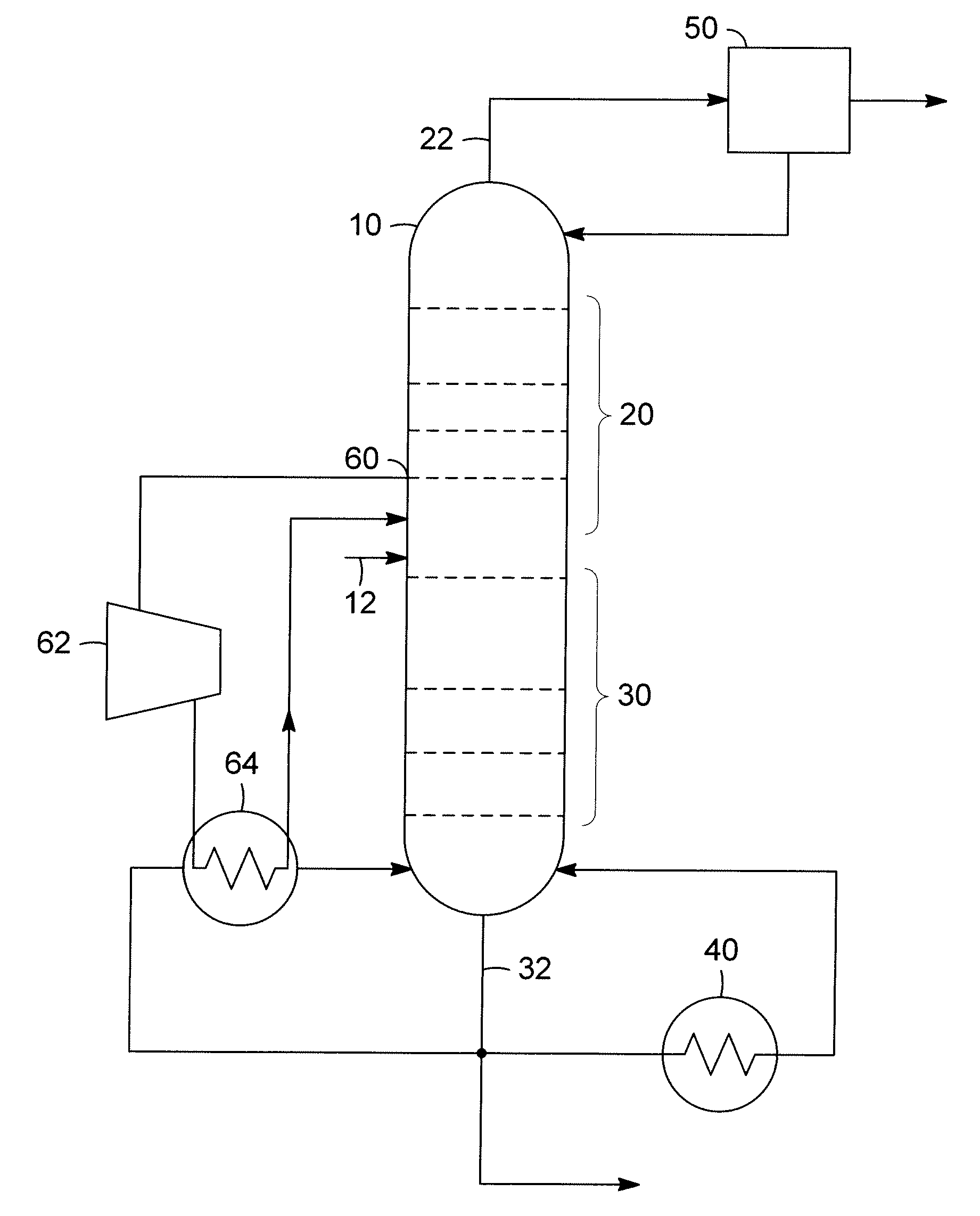
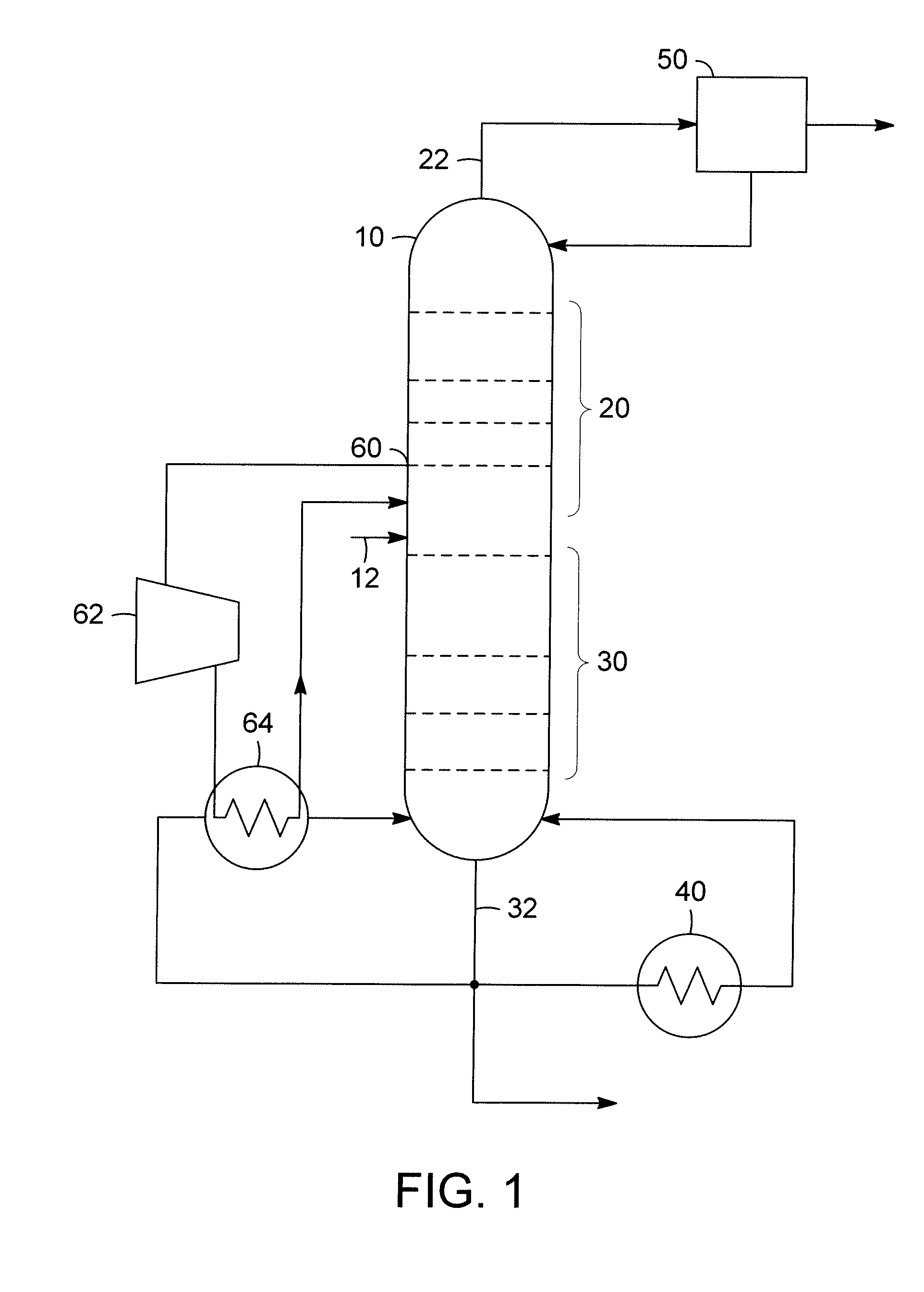
[0011]The separation of fluids is well known in art, and separation by distillation is a common means for separating two or more liquids. A distillation process operates on the principle of different liquid components in a mixture have different volatilities, and therefore will develop an equilibrium where for the more volatile component, the vapor phase has a higher concentration relative to that components concentration in the liquid phase.

[0012]In a continuous distillation process, the basic equipment comprises a distillation column having a plurality of plates, an overhead condenser, and a bottoms reboiler. In general the distillation column is a vertically oriented, cylindrical vessel and comprises an inlet for admitting the fluid to be separated, a rectifying section that is above the inlet, and a stripping section that is below the fluid. The plates are typically sieve trays or bubble cap trays, or other trays that allow the liquid to flow across and the vapor to percolate up...


PUM


Abstract

A process for reducing the energy consumption of a distillation column is disclosed. The process includes drawing off an intermediate vapor stream from the rectification section of the distillation column. The vapor stream is compressed and the heat in the vapor stream is exchanged with a portion of the liquid bottoms stream. The heat transfer condenses a portion of the vapor stream, while vaporizing the liquid bottoms stream.

Description

FIELD OF THE INVENTION[0001]This invention relates to the separation of hydrocarbons. Specifically, the invention relates to improving the energy usage for the separation of hydrocarbon components that have similar boiling points through distillation.BACKGROUND OF THE INVENTION[0002]The separation of hydrocarbons is a basic process in the petroleum industry. Petroleum is a mixture of many hydrocarbon compounds and the compounds are separated and used for different purposes, such as fuel, lubricants, feedstock to polymer plants, etc. One method of separation in the petroleum industry is distillation. Distillation is a method of separation that is based on a difference in the relative volatilities of the components in a mixture, and therefore differences in the composition between a liquid mixture and a vapor formed from the liquid mixture. In a standard continuous distillation process involving multiple stages, the differences in composition allows for partial separation at each stag...

Claims


Application Information

Patent Timeline
IPC IPC(8): B01D3/14
CPCB01D3/007B01D3/14Y10S203/08Y10S203/20Y10S203/04Y02B30/52
Inventor SECHRIST, PAUL A.WEGERER, DAVID A.
Owner UOP LLC
Why Eureka
Try Eureka