Eureka AIR delivers breakthrough ideas for toughest innovation challenges, trusted by R&D personnel around the world.

Multi-battery system for high voltage applications with proportional power sharing

Active Publication Date: 2010-04-29
STRYTEN ENERGY LLC
View PDF3 Cites 17 Cited by
  • Summary
  • Abstract
  • Description
  • Claims
  • Application Information

AI Technical Summary

Benefits of technology

[0009]In accordance with the present invention there is provided a multi-battery system for high-voltage applications having a proportional power sharing scheme. In one embodiment of the present invention there is provided at least two batteries coupled to a respective at least two energy storage means. The energy storage means are controlled by a master monitoring circuit connected at the point of load. Each energy storage means may be additionally controlled by a monitoring circuit on its respective battery. The energy storage means will store more power when connected to a battery having a higher output voltage and hence a higher state of charge. A battery with a lower state of charge will experience a more severe voltage drop under heavier loads. This is detected by the monitoring circuit and the system will

Problems solved by technology

The requirement for redundancy can result in very large and unwieldy systems due to the duplication and even triplication of system components.
The inability to do so may result in the UPS continually relying upon a depleted battery bank for input voltage.
Overtime, the depleted batteries will fail to charge and the UPS becomes less reliable.
This results in equal power consumption from each battery.
However such systems can still fail to take into account the state of charge of the batteries.
This will result in a depleted battery continually being called upon to share a load it is not capable of producing.
In the end, the battery will fail and the system reliability will be compromised.
Another situation can occur in very large power systems where perhaps hundreds of batteries are used.
A battery with a lower state of charge will experience a more severe voltage drop under heavier loads.

Method used


Image

  • Multi-battery system for high voltage applications with proportional power sharing
  • Multi-battery system for high voltage applications with proportional power sharing
  • Multi-battery system for high voltage applications with proportional power sharing

Examples


Embodiment Construction

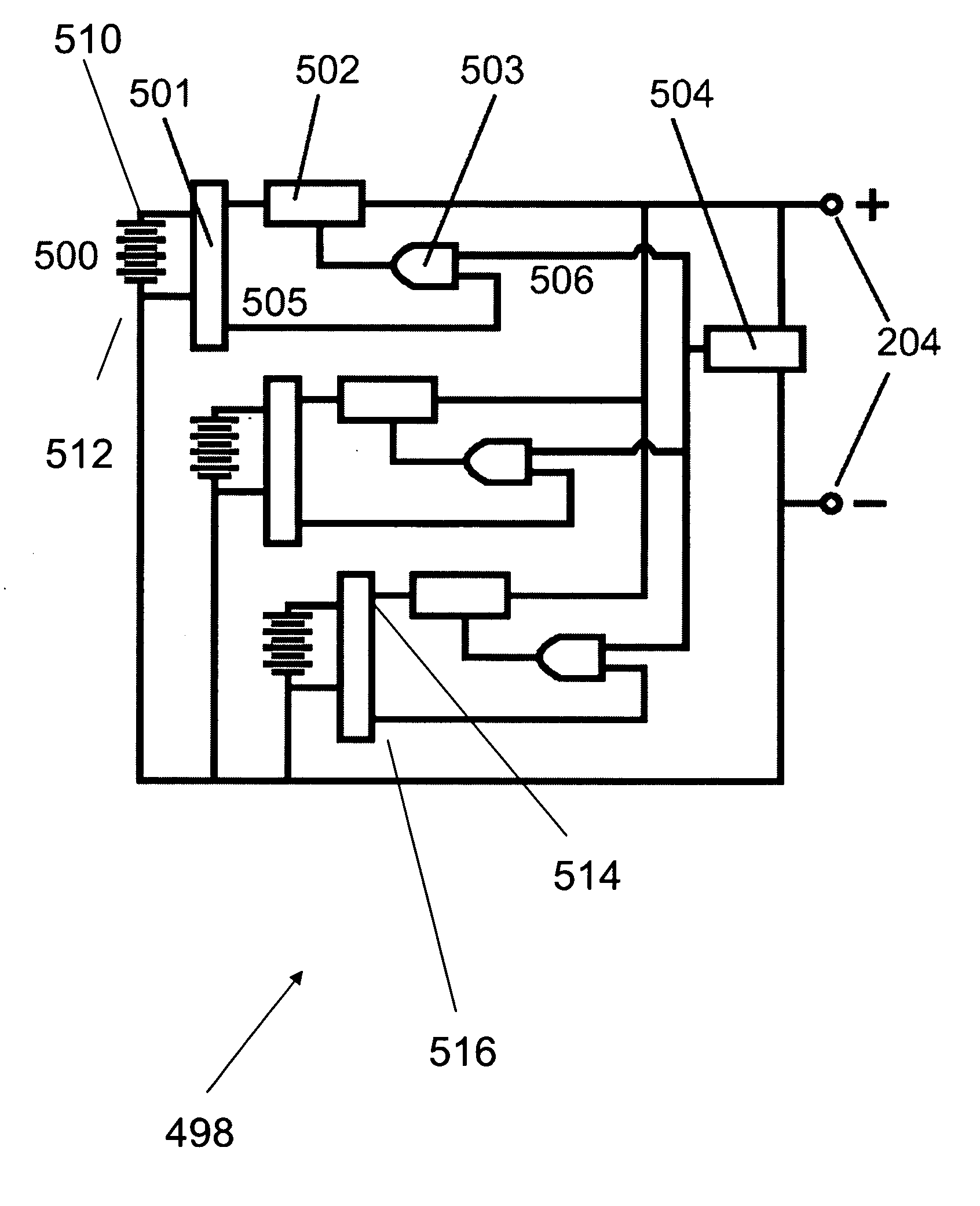
[0026]Referring now to FIG. 5, there is shown one embodiment of the present invention that overcomes the deficiencies discussed above. The invention comprise a circuit 498 that comprises a plurality of battery circuits each comprising a battery 500 that is connected to and monitored by protection means 501. Generally the circuit will have at least two batteries and each battery will have a battery positive 510 and a battery negative 512 terminal. This combination of batteries will provide the system with the desired level of voltage output and reliability. Protection means 501 is connected across the battery positive and negative terminals. The output of the protection means is through protection means positive 514 and negative 516 terminals. The protection means output is feed into energy storage means 502 connected to the positive terminal of protection means. The energy storage means stores energy when it receives a true digital control signal from a logic circuit means 503. The ...


PUM


Abstract

A multi-battery system for high-voltage applications with proportional power sharing comprises a circuit having a circuit positive and a circuit negative terminal. At least two batteries are provided to combine to deliver required system power. The batteries are connected to a protection circuit, energy storage means, system output voltage sensing means and a logic gate. Protection means generates a protection signal and the voltage sensing means generates an enabling signal that are fed into the logic gate as true signals to generate a true control signal. The true control signal causes the energy storage means to discharge. The digital enabling signal for each of the circuits is time-shifted by a time “t” so that at any time one of the circuits is discharging and one of the at least two circuits is charging during said time “t”.

Description

CROSS-REFERENCE TO RELATED APPLICATIONS[0001]None.BACKGROUND [0002]1. Field of the Invention[0003]This invention relates to a method or apparatus for controlled or regulated charging, discharging, or combined charging and discharging of one or more voltaic cells, batteries, or capacitors. Specifically, this invention relates to a multi-battery system for high-voltage applications with proportional power sharing.[0004]2. Description of the Prior Art[0005]A number of operationally critical applications have power requirements that require high voltages and currents and require a high degree of availability and reliability. One way of ensuring high reliability is to have a high degree of redundancy in as many components of the system as possible. In battery operated systems the most critical component is often the batteries and in high voltage applications a large number of batteries may be required to produce the necessary power output. For example, in an uninterruptible power supply ...

Claims


Application Information

Patent Timeline
IPC IPC(8): H02H3/20
CPCH02J7/0013H02J2007/0067H02J7/0021H02J7/0025H02J7/005H02J7/0018
Inventor CARKNER, STEVEABDELSAMIE, AHMED
Owner STRYTEN ENERGY LLC
Why Eureka
Eureka Blog
Learn More