Method and device for graft fenestration

a graft and fenestration technology, applied in the field of graft fenestration, can solve the problems of additional technical challenges, life-threatening complications for patients with acute aortic dissection, and the complexity of total alignment of these pre-made fenestrations still requires partial device deploymen

Inactive Publication Date: 2010-04-29
MCLACHLAN CRIAG STEVEN +2
View PDF9 Cites 17 Cited by
  • Summary
  • Abstract
  • Description
  • Claims
  • Application Information

AI Technical Summary

Benefits of technology

[0032]The legs on a catheter delivery system or graft can be used to perform the steps of the method of crating a void in which to create a fenestration safely.
[0080]3) The space between the endograft and large vessel lumen permits imaging of side branches that emanate from the inner lumen of the targeted blood vessel to be grafted,

Problems solved by technology

Patients with acute aortic dissection may have life threatening complications manifested by end organ ischemia.
Unfortunately, not all patients diagnosed with aortic disease (in particular aneurysm and or dissection) are presently considered to be candidates for endovascular grafting.
This is largely due to the fact that most endovascular grafting systems of the prior art are not designed for use in regions of the aorta from which side branches (i.e., carotid, innominate, subclavian, intercostal, superior mesenteric, celiac or renal arteries) extend.
The deployment of endovascular grafts within regions of the aorta from which branch arteries extend (e.g., regions of the aorta from which the renal, superior mesenteric, celiac, intercostal, and / or subclavian arteries emanate) present additional technical challenges because, in those cases, the endovascular graft must be designed, implanted and maintained in a manner which does not impair the flow of blood into the branch arteries or vessels.
However, the complexity of total alignment of these pre-made fenestrations still requires partial device deployment, orientation markers on the endograft, and complex intra-operative angiography enable maneuvering of the fenestration over the orifice of the target vessel with the aid of guiding catheters, however it does not take into account the precise geometry of each individual patient and the ability to correctly align the endograft in a period of time that does not cause significant ischemia or hypoxia to the targeted tissues.
However, such fenestrations do not form discrete conduit(s) through which blood is channeled into each branch artery.
As a result, the area surrounding the fenestrations could be prone to leakage of blood into the space between the outer surface of the aortic graft and the surrounding aortic wall especially if alignment is not exact.
A further problem that always remains with each endograft procedure is the risk and need for potential bailout after an incorrect endograft landing where the graft covers a vessel side-branch; therefore methods that permit rapid in situ fenestration are necessary.
In these cases a pre-fenestrated endograft would not repair a tissue related problem.
2004 April;11(2):170-4) of endovascular fenestration: 1. There study has no specific fenestration device but simply refers to the off label use of a guide wire to puncture the graft and thereby result in an unpredictable and possible dangerous procedure; 2. Such graft entry via “off label” use of a guide wire could only be achieved from a branch vessel accessed peripherally via percutaneous retrograde access.
This thereby limits the procedures applicability with mesenteric and renal vessels, which are not amenable to this approach.

Method used


Image

  • Method and device for graft fenestration
  • Method and device for graft fenestration
  • Method and device for graft fenestration

Examples


Embodiment Construction

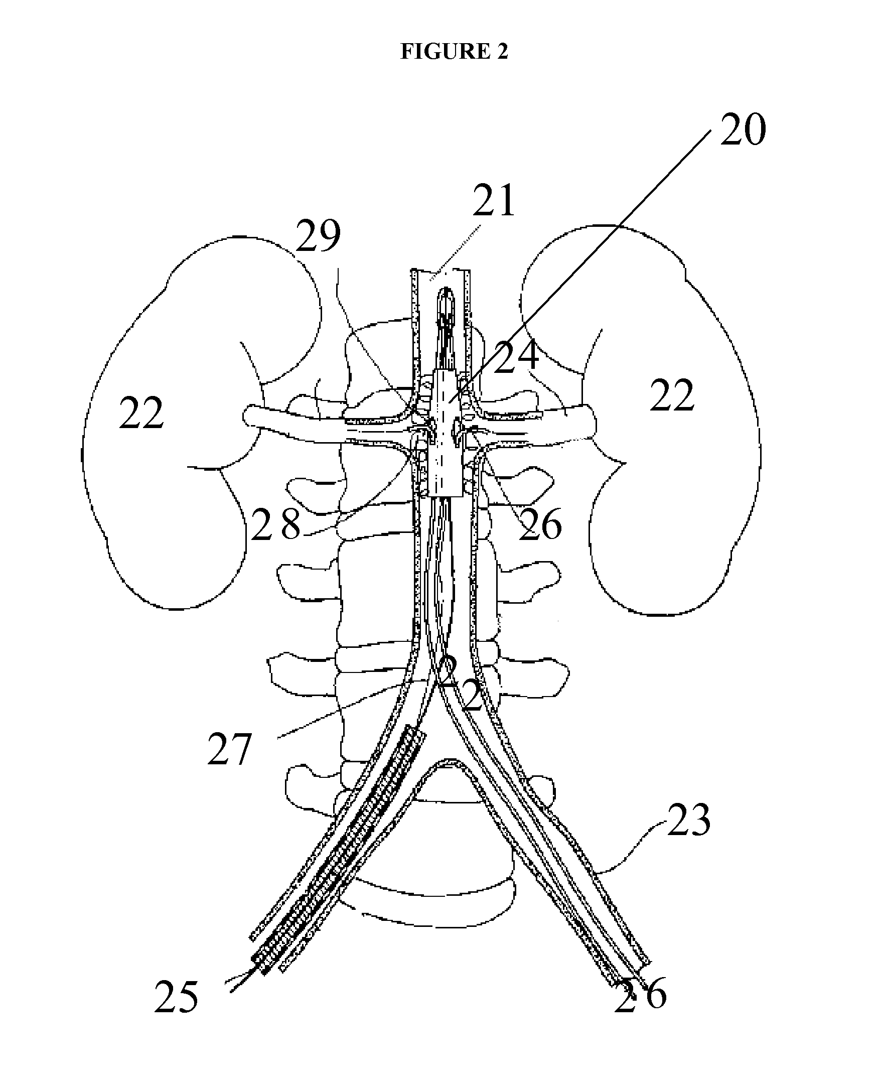
[0092]The present invention relates generally to the field of the treatment of aortic disease and in particular to endoluminal aortic grafts, which allow accurate placement of a covered stent or tube in the aorta and a means to create fenestrations within the covered stent or tube and or surrounding tissue. In particular the covered stent is capable of being deployed and positioned anywhere within the aorta and there is a means to create fenestrations in situ in vivo. Fenestrations can be created within the graft or surrounding tissues. These fenestrations serve one of two purposes: firstly to prevent occlusion of side branches off the aorta by aortic tissue and or by the graft when it is fully deployed and secondly to reestablish blood flow such as in an aortic dissection that may complicate side branch blood flow by means of a dissection flap.

[0093]A graft that is placed in the aorta or other body lumen can be any of the following or combinations thereof: a stent that are covered ...


PUM


Abstract

The present invention provides a method of creating fenestrations in situ through a body wall of a covered stent or endograft lumen. The fenestration is aligned with a side branch of the body lumen. The created fenestration of the graft is in communication with a side branch. That is the patent or open side branch permits fluid communication from the main lumen across the stented or endograft lumen. Tools are described to carry out these fenestrations for either a graft or a side branch that is communication with a graft in vivo. Further these tools are described to carry out these methods for both in situ branch tissue and graft fenestration and alignment of the fenestrations The present invention provides a method for in situ fenestration, the method including the steps of: positioning a graft or graft unit in situ within a body lumen and forming an initial void or space between graft unit and the inner wall of the body lumen. The present invention also provides a catheter including a: a) a distal tip that can perform a piercing and opening action; and or b) a distal tip rotates by means of a drive shaft within the catheter to cut and or open a tissue or graft to form fenestration; and or c) a stabilization means to stabilize the position of the catheter during fenestration.

Description

FIELD OF THE INVENTION[0001]The present invention relates to in vivo (in situ) creation of fenestration of either a graft and or biocompatible material and or graft associated biological tissue. A method and device is described for fenestration that pertains to covered stents or endograft following their placement within a body lumen.[0002]The fenestrations are created in situ through a body wall of a covered stent or endograft lumen. The fenestration is aligned with a side branch of the body lumen. The created fenestration of the graft is in communication with a side branch. That is the patent side branch permits fluid communication from the main lumen across the stented or endograft lumen. Tools are described to carry out these fenestrations for either a graft or a side branch that is communication with a graft in vivo. Further these tools are described to carry out these methods for both in situ branch tissue and graft fenestration and alignment of the fenestrations.BACKGROUND[00...

Claims


Application Information

Patent Timeline
Patent Type & Authority Applications(United States)
IPC IPC(8): A61B17/34A61F2/06
CPCA61B17/32002A61F2/06A61F2002/075A61F2002/061A61F2002/072A61F2/07
Inventor MCLACHLAN, CRIAG STEVENMOSSOP, PETERNIXON, IAN
Owner MCLACHLAN CRIAG STEVEN
Why Eureka
Try Eureka