
Stent and method for making a stent

a stent and a technology for making stents, applied in the field of stents and a method for making stents, can solve the problems of affecting the stent thrombosis, the formation of acute, sub-acute or potential late stent thrombosis, the inability to vary the type of coated drugs, the inability to change the release rate, etc., and achieve the effect of achieving the same release rate, efficient and cost-

Inactive Publication Date: 2010-04-29
ABBOTT CARDIOVASCULAR
View PDF7 Cites 9 Cited by
  • Summary
  • Abstract
  • Description
  • Claims
  • Application Information

AI Technical Summary

Benefits of technology

"The present invention relates to a stent that can release drugs to alleviate problems such as restenosis and stent thrombosis. The stent can release drugs at different rates in different areas, and can also release different types of drugs at different times. The stent can be made efficiently and cost-effectively, and can be adapted to the specific needs of patients. The stent includes a body, a layer of therapeutic agent, and a sealant layer. The sealant layer can have one or more through holes that allow the therapeutic agent to be released. The stent can help reduce blood flow recirculation and stagnation, which can lead to restenosis and stent thrombosis."

Problems solved by technology

Additionally, flow recirculation or stagnation, combined with the inflammatory response prompted by local injury generated by stent deployment, may potentially lead to the formation of acute, sub-acute, or potential late stent thrombosis.
It may also lead to platelet deposition, aggregation, and accumulation.
It is very difficult, if not impossible, to vary the types of coated drugs, or to vary the release rate of the coated drugs, from one area of the stent to another area.

Method used


Image

  • Stent and method for making a stent
  • Stent and method for making a stent
  • Stent and method for making a stent

Examples


Embodiment Construction

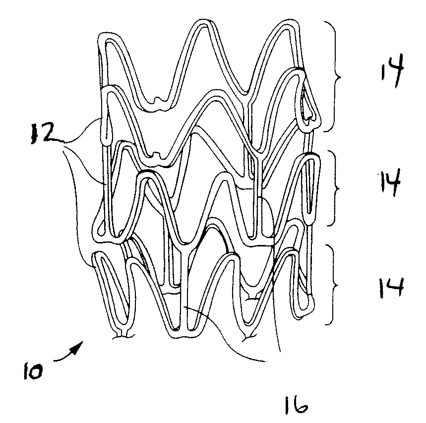
[0051]A preferred embodiment of the stent according to the present invention may have the configuration shown in FIG. 1. The stent 10 shown in FIG. 1 includes a plurality of struts 12 that are radially expandable. The struts 12 may be interconnected by connecting elements 14 that are disposed between adjacent struts 12, leaving lateral openings or gaps 16 between the adjacent struts 12. The struts 12 and connecting elements 14 define a tubular stent body having an outer, tissue-contacting surface and an inner surface.

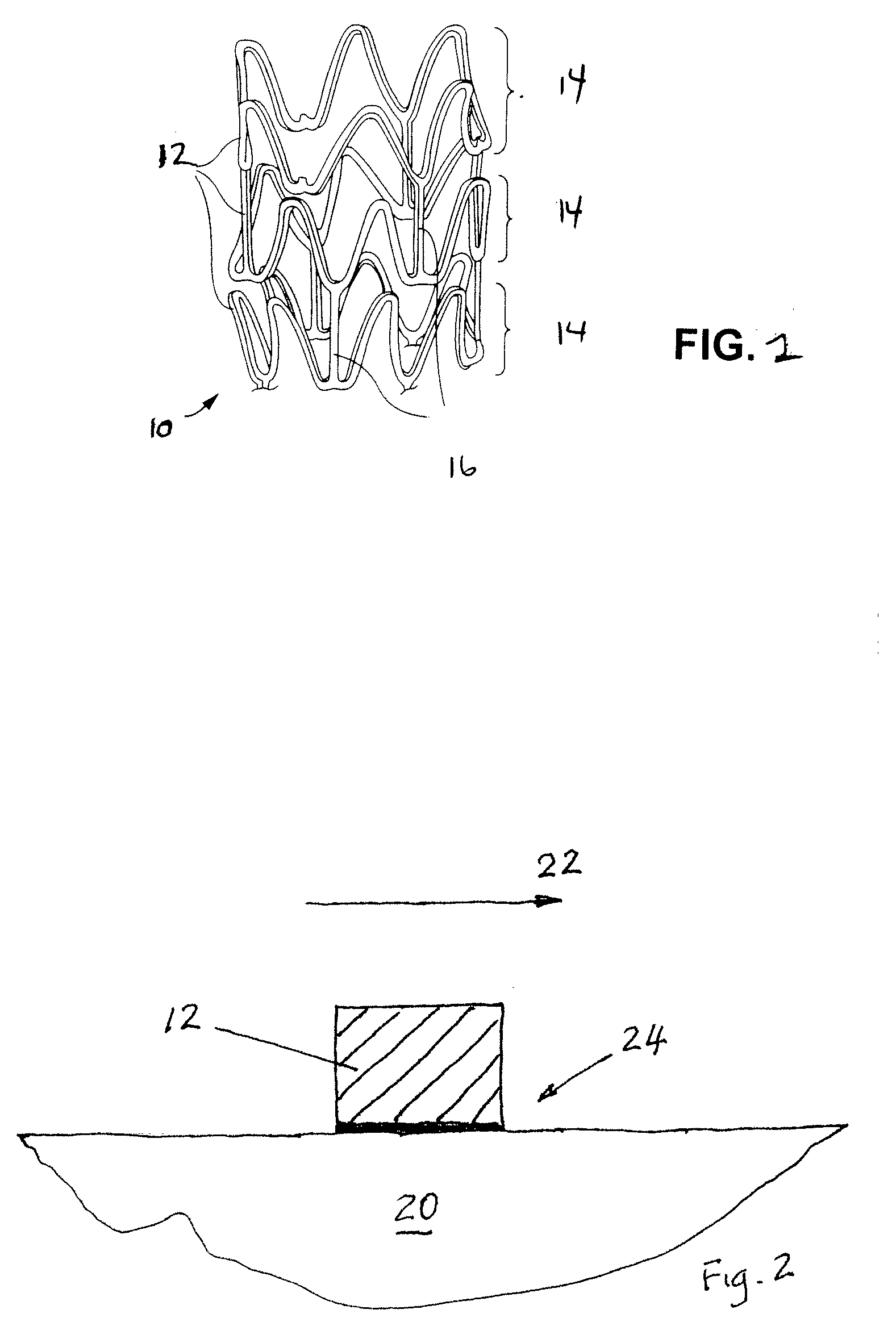
[0052]In the illustrated preferred embodiment of the present invention, a first area of the stent surface may have different drug release characteristics than a second area of the stent surface. The first area may be adjacent or may border the area 24 of blood flow recirculation or stagnation, as shown in FIG. 2, and therefore require certain drug release characteristics. And the second area may be remote from the area 24 of blood flow recirculation or stagnation and th...


PUM


Abstract

A stent includes a body, a layer of therapeutic agent over at least a section of the body, and a sealant layer over the layer of therapeutic agent. The sealant layer includes a through hole that allows release of the therapeutic agent of the therapeutic agent layer through the through hole when the stent is deployed in a blood vessel.

Description

FIELD OF THE INVENTION[0001]This invention relates to a stent and a method for making a stent.BACKGROUND OF THE INVENTION[0002]Minimally invasive surgical procedures, such as percutaneous transluminal coronary angioplasty (PTCA), have become increasingly common. A PTCA procedure involves the insertion of a catheter into a coronary artery to position an angioplasty balloon at the site of a stenotic lesion that is at least partially blocking the coronary artery. The balloon is then inflated to compress the stenosis and to widen the lumen in order to allow an efficient flow of blood through the coronary artery.[0003]Following PTCA and other stenotic treatment procedures, a significant number of patients experience restenosis or other vascular blockage problems. These problems are prone to arise at the site of the former stenosis.[0004]In order to help avoid restenosis and other similar problems, a stent may be implanted into the vessel at the site of the former stenosis with a stent de...

Claims


Application Information

Patent Timeline
Patent Type & Authority Applications(United States)
IPC IPC(8): A61F2/06A61B19/00
CPCA61F2240/001A61F2/91
Inventor OZKAN, ARZU M.ABUNASSAR, CHAD JOSEPH
Owner ABBOTT CARDIOVASCULAR
Learn More