
Manufacture of Controlled Rate Dissolving Materials

a dissolving material and controlled rate technology, applied in the field of new materials, can solve the problems of limited strength, poor reliability, widespread adoption, etc., and achieve the effects of enhancing mechanical properties of composite materials, ductility and/or tensile strength, and low cathode particle loading

Active Publication Date: 2017-02-02
TERVES
View PDF2 Cites 5 Cited by
  • Summary
  • Abstract
  • Description
  • Claims
  • Application Information

AI Technical Summary

Benefits of technology

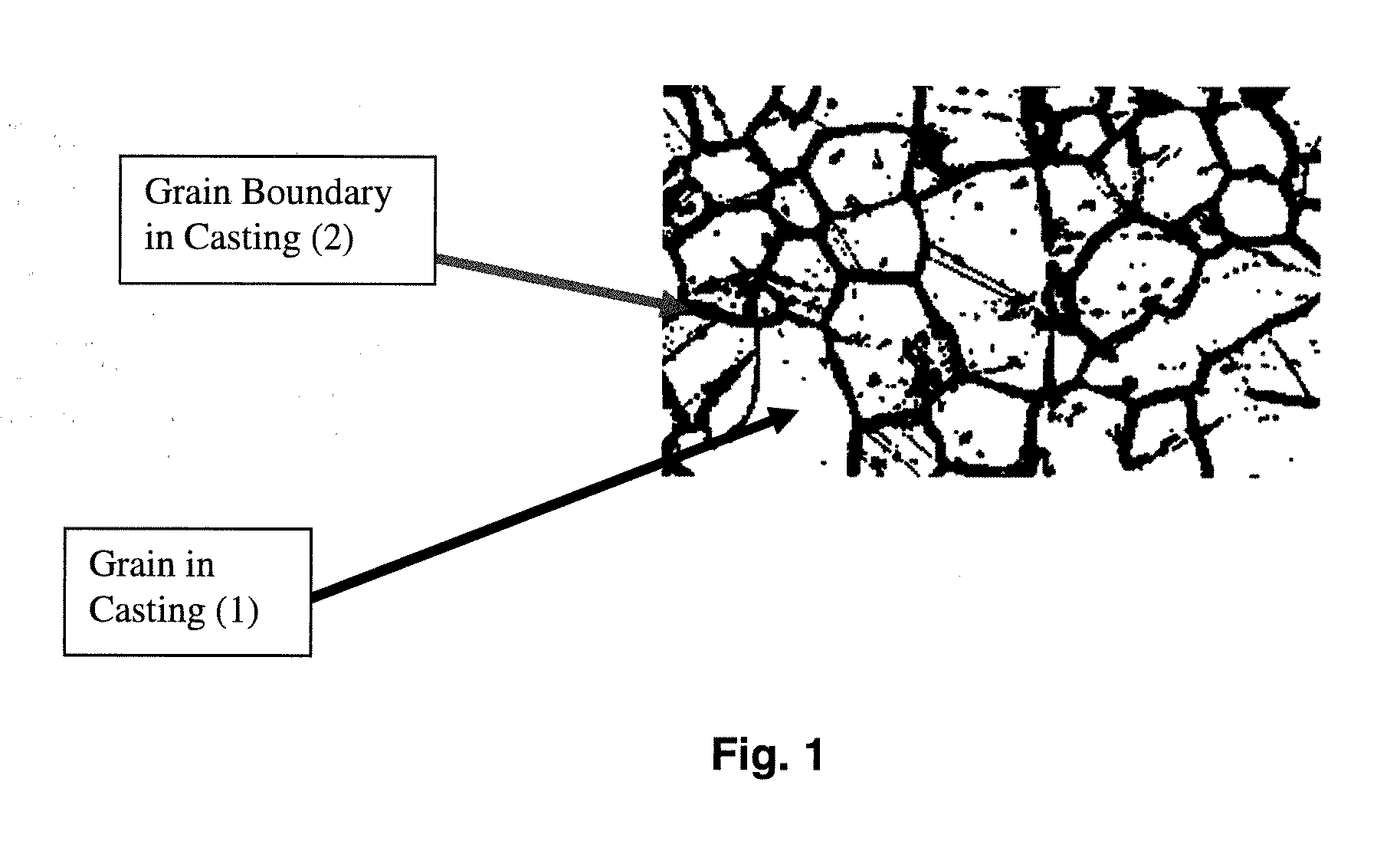
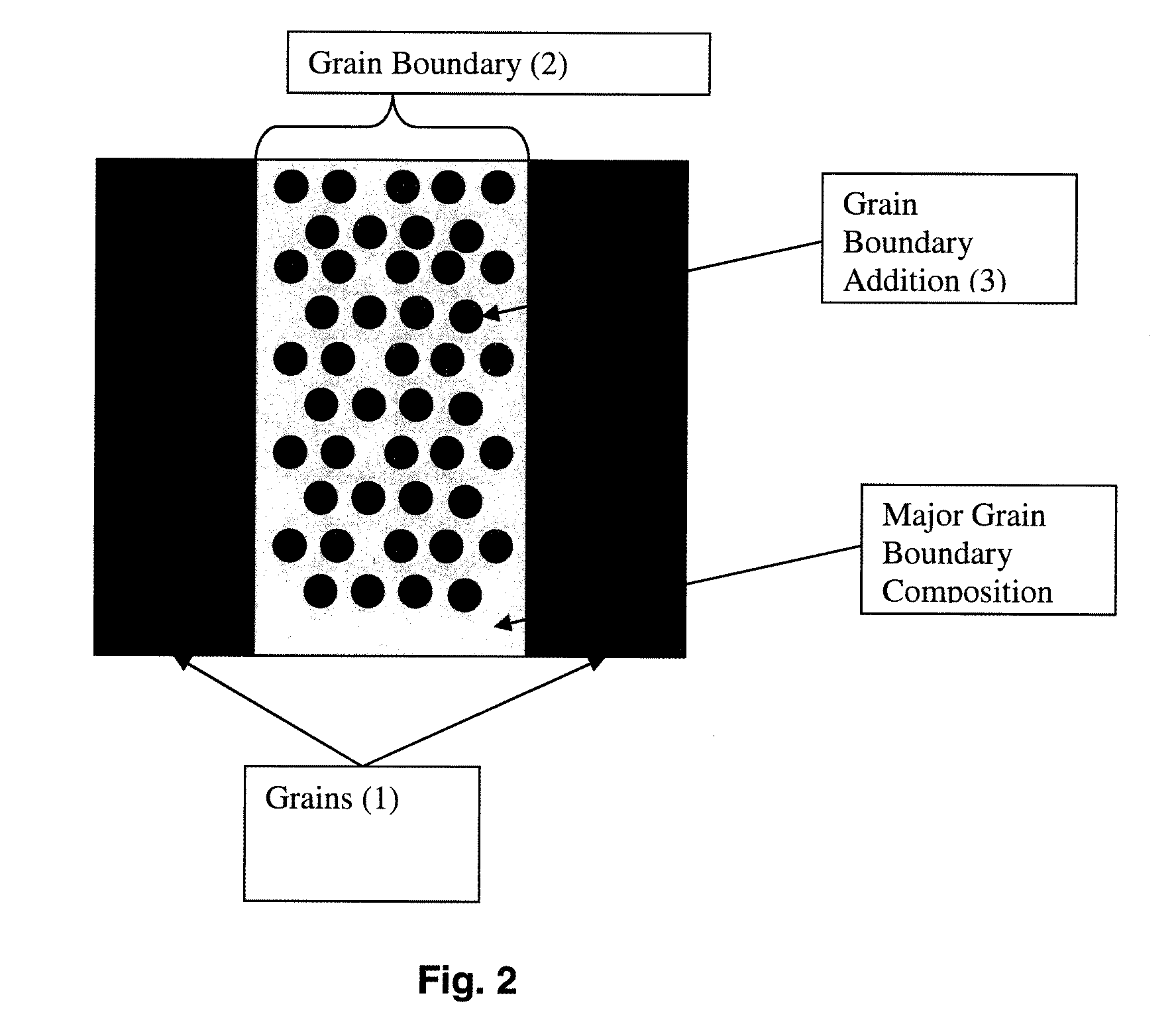
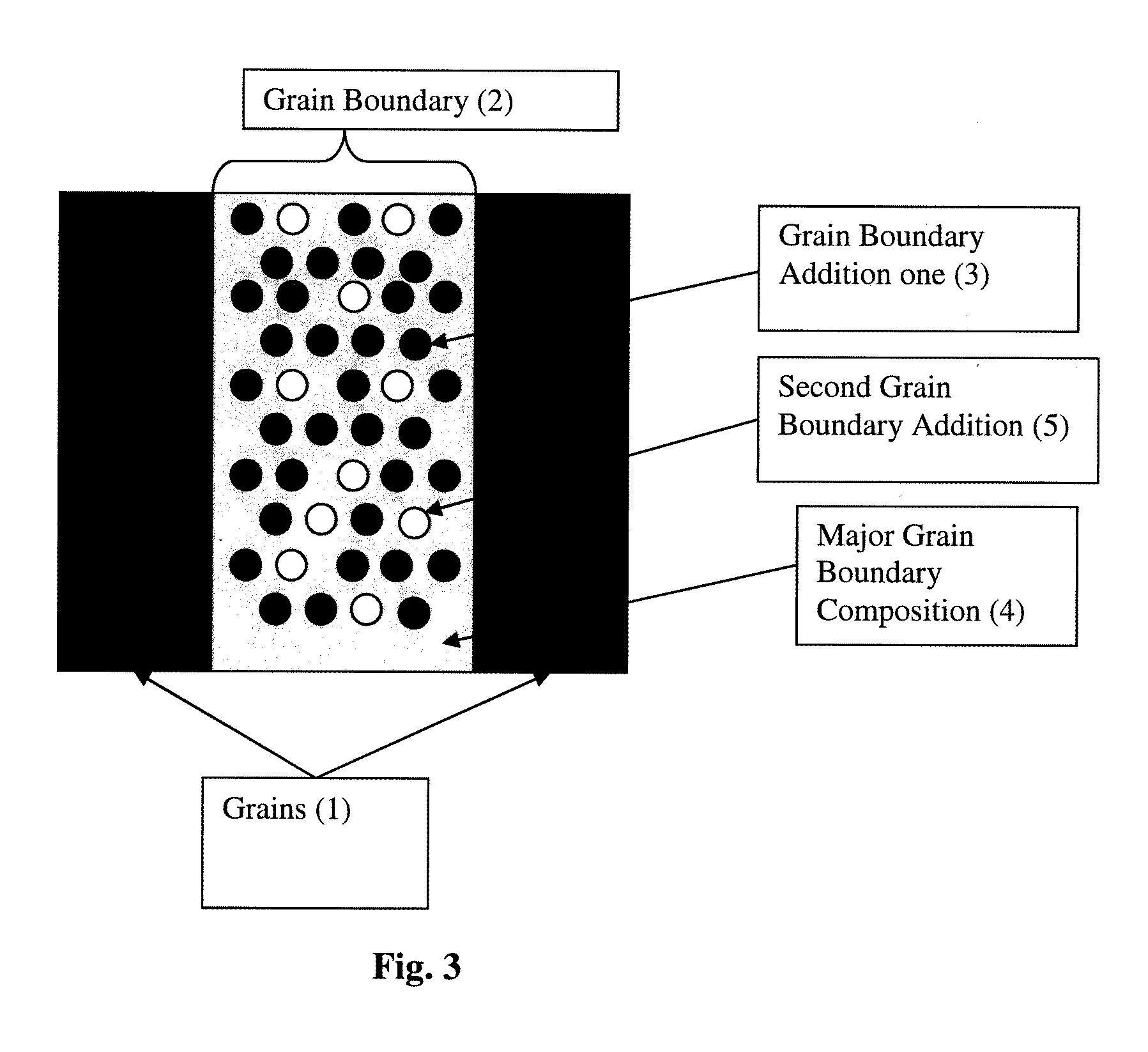
[0005]The present invention is directed to a castable, moldable, or extrudable structure using a metal or metallic primary alloy. Non-limiting metals include aluminum, magnesium, aluminum and zinc. Non-limiting metal alloys include alloys of aluminum, magnesium, aluminum and zinc. One or more additives are added to the metallic primary metal or alloy to form a novel composite. The one or more additives are selected and used in quantities so that the grain boundaries of the novel composite contain a desired composition and morphology to achieve a specific galvanic corrosion rate in the entire composite or along the grain boundaries of the composite. The invention adopts a feature that is usually a negative in traditional casting practices wherein insoluble particles are pushed to the grain boundary during the solidification of the melt. This feature results in the ability to control where the particles are located in the final casting, as well as the surface area ratio which enables the use of lower cathode particle loadings compared to a powder metallurgical or alloyed composite to achieve the same dissolution rates. The addition of insoluble particles to the metal or metal alloy can be used to enhance mechanical properties of the composite, such as ductility and / or tensile strength, when added as submicron particles. The final casting can optionally be enhanced by heat treatment as well as deformation processing, such as extrusion, forging, or rolling, to further improve the strength of the final composite over the as-cast material. The deformation processing achieves strengthening by reducing the grain size of the metal alloy composite. Further enhancements, such as traditional alloy heat treatments such as solutionizing, aging and cold working, can optionally be used without dissolution impact if further improvements are desired. Because galvanic corrosion is driven by both the electro potential between the anode and cathode phase, as well as the exposed surface area of the two phases, the rate of corrosion can also be controlled through adjustment of cathode particle size, while not increasing or decreasing the volume or weight fraction of the addition, and / or by changing the volume / weight fraction without changing the particle size.
[0006]In one non-limiting aspect of the invention, a cast structure can be made into almost any shape. During solidification, the active reinforcement phases are pushed to the grain boundaries and the grain boundary composition is modified to achieve the desired dissolution rate. The galvanic corrosion can be engineered to only affect the grain boundaries and / or can also affect the grains based on composition. This feature can be used to enable fast dissolutions of high-strength lightweight alloy composites with significantly less active (cathode) reinforcement phases compared to other processes.

Problems solved by technology

While these systems have enjoyed modest success in reducing well completion costs, their consistency and ability to specifically control dissolution rates in specific solutions, as well as other drawbacks such as limited strength and poor reliability, have impacted their ubiquitous adoption.

Method used


Image

  • Manufacture of Controlled Rate Dissolving Materials
  • Manufacture of Controlled Rate Dissolving Materials
  • Manufacture of Controlled Rate Dissolving Materials

Examples


example 1

[0061]An AZ91D magnesium alloy having 9 wt. % aluminum, 1 wt. % zinc and 90 wt. % magnesium was melted to above 700° C. About 16 wt. % of 75 um iron particles were added to the melt and dispersed. The melt was cast into a steel mold. The iron particles did not fully melt during the mixing and casting processes. The cast material exhibited a tensile strength of about 26 ksi, and an elongation of about 3%. The cast material dissolved at a rate of about 2.5 mg / cm2-min in a 3% KCl solution at 20° C. The material dissolved at a rate of 60 mg / cm2-hr in a 3% KCl solution at 65° C. The material dissolved at a rate of 325 mg / cm2-hr. in a 3% KCl solution at 90° C. The dissolving rate of metal cast structure for each these test was generally constant. The iron particles were less than 1 μm, but were not nanoparticles. However, the iron particles could be nanoparticles, and such addition would change the dissolving rate of metal cast structure.

example 2

[0062]An AZ91D magnesium alloy having 9 wt. % aluminum, 1 wt. % zinc and 90 wt. % magnesium was melted to above 700° C. About 2 wt. % 75 um iron particles were added to the melt and dispersed. The melt was cast into steel molds. The iron particles did not fully melt during the mixing and casting processes. The material exhibited a tensile strength of 26 ksi, and an elongation of 4%. The material dissolved at a rate of 0.2 mg / cm2-min in a 3% KCl solution at 20° C. The material dissolved at a rate of 1 mg / cm2-hr in a 3% KCl solution at 65° C. The material dissolved at a rate of 10 mg / cm2-hr in a 3% KCl solution at 90° C. The dissolving rate of metal cast structure for each these test was generally constant. The iron particles were less than 1 μm, but were not nanoparticles. However, the iron particles could be nanoparticles, and such addition would change the dissolving rate of metal cast structure.

example 3

[0063]An AZ91D magnesium alloy having 9 wt. % aluminum, 1 wt. % zinc and 90 wt. % magnesium was melted to above 700° C. About 2 wt. % nano iron particles and about 2 wt. % nano graphite particles were added to the composite using ultrasonic mixing. The melt was cast into steel molds. The iron particles and graphite particles did not fully melt during the mixing and casting processes. The material dissolved at a rate of 2 mg / cm2-min in a 3% KCl solution at 20° C. The material dissolved at a rate of 20 mg / cm2-hr in a 3% KCl solution at 65° C. The material dissolved at a rate of 100 mg / cm2-hr in a 3% Ka solution at 90° C. The dissolving rate of metal cast structure for each these test was generally constant.


PUM

PropertyMeasurementUnit
melting pointaaaaaaaaaa
particle sizeaaaaaaaaaa
surface areaaaaaaaaaaa

Abstract

A castable, moldable, or extrudable structure using a metallic base metal or base metal alloy. One or more insoluble additives are added to the metallic base metal or base metal alloy so that the grain boundaries of the castable, moldable, or extrudable structure includes a composition and morphology to achieve a specific galvanic corrosion rates partially or throughout the structure or along the grain boundaries of the structure. The insoluble additives can be used to enhance the mechanical properties of the structure, such as ductility and / or tensile strength. The insoluble particles generally have a submicron particle size. The final structure can be enhanced by heat treatment, as well as deformation processing such as extrusion, forging, or rolling, to further improve the strength of the final structure as compared to the non-enhanced structure.

Description

[0001]The present invention is a divisional of U.S. application Ser. No. 14 / 627,236 filed Feb. 20, 2015, which in turn claims priority on U.S. Provisional Application Ser. No. 61 / 942,879 filed Feb. 21, 2014, which is incorporated herein by reference.FIELD OF THE INVENTION[0002]The invention is directed to a novel material for use as a dissolvable structure in oil drilling. Specifically, the invention is directed to a ball or other structure in a well drilling or completion operation, such as a structure that is seated in a hydraulic operation, that can be dissolved away after use so that that no drilling or removal of the structure is necessary. Primarily, dissolution is measured as the time the ball removes itself from the seat or can become free floating in the system. Secondarily, dissolution is measured in the time the ball is fully dissolved into submicron particles. Furthermore, the novel material of the present invention can be used in other well structures that also desire t...

Claims


Application Information

Patent Timeline
Patent Type & Authority Applications(United States)
IPC IPC(8): B22D23/06C22C1/03B22D21/00B22D25/06C22C49/04B22D27/08B22D27/11B22F1/00C22C49/14C22C23/02B22D27/02B22F1/062
CPCB22D23/06C22C23/02C22C1/03B22D21/007B22D25/06B22D27/02B22F2304/05B22D27/11B22F1/004C22C49/14C22C49/04B22F2301/35B22D27/08C22C49/02B22F2999/00B22D19/14B22D21/04B22D27/00C22C23/00C22C47/08B22F1/062B22F2202/01
Inventor SHERMAN, ANDREWDOUD, BRIANFARKAS, NICHOLAS
Owner TERVES
Learn More