Energy accumulator comprising a switched reluctance machine

a technology of energy accumulator and switch, which is applied in mechanical energy handling, electrical apparatus, support/enclose/case, etc., can solve the problems of limiting the rotational speed of the energy storage device, increasing the stress, and increasing the tensile stress in the central and inner surfaces, so as to achieve the effect of increasing the rotational speed of the rotor

Inactive Publication Date: 2010-05-06
COMPACT DYNAMICS
View PDF7 Cites 6 Cited by
  • Summary
  • Abstract
  • Description
  • Claims
  • Application Information

AI Technical Summary

Benefits of technology

[0012]The material strength of the sheet-metal discs of the rotor, or of the rotating body, in this case constitutes a factor limiting the rotational speed of the energy storage device. From the relationship Ekin=½·J·ω2, wherein Ekin is the kinetic energy of the rotating body (rotor and fly-mass), and consequently of the energy storage device in joules, J is the mass moment of inertia in kgm2, and ω is the angular velocity of the rotating body in s−1, i

Problems solved by technology

However, the static preloading increases the stresses, resulting from centrifugal forces, in the peripheral surfaces, and reduces the greater tensile stresses in the central and inner surfaces of the discs.
The material strength of the sheet-metal discs of the rotor, or of the rotating body, in this case constitutes a factor limiti

Method used


Image

  • Energy accumulator comprising a switched reluctance machine
  • Energy accumulator comprising a switched reluctance machine
  • Energy accumulator comprising a switched reluctance machine

Examples


Embodiment Construction

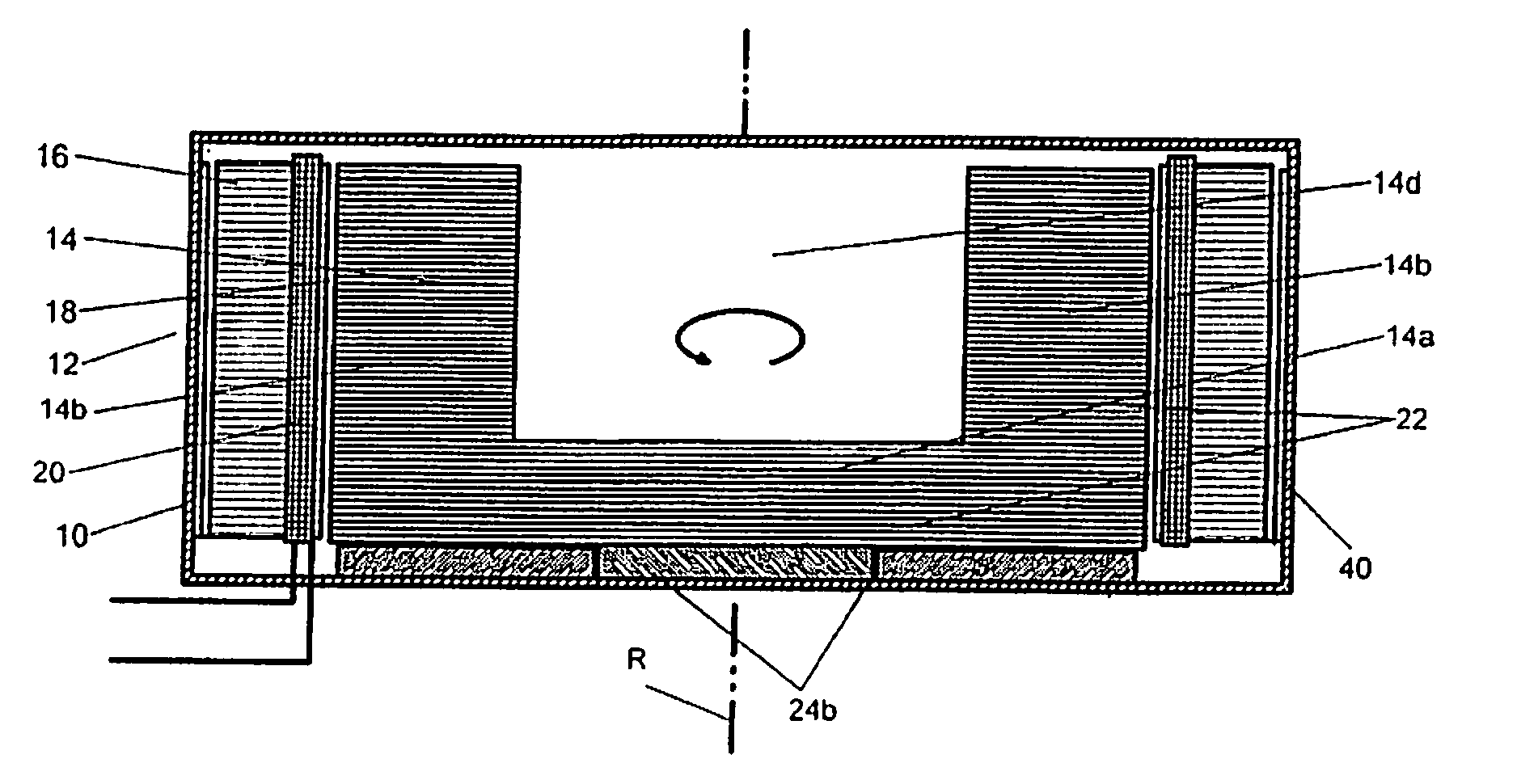
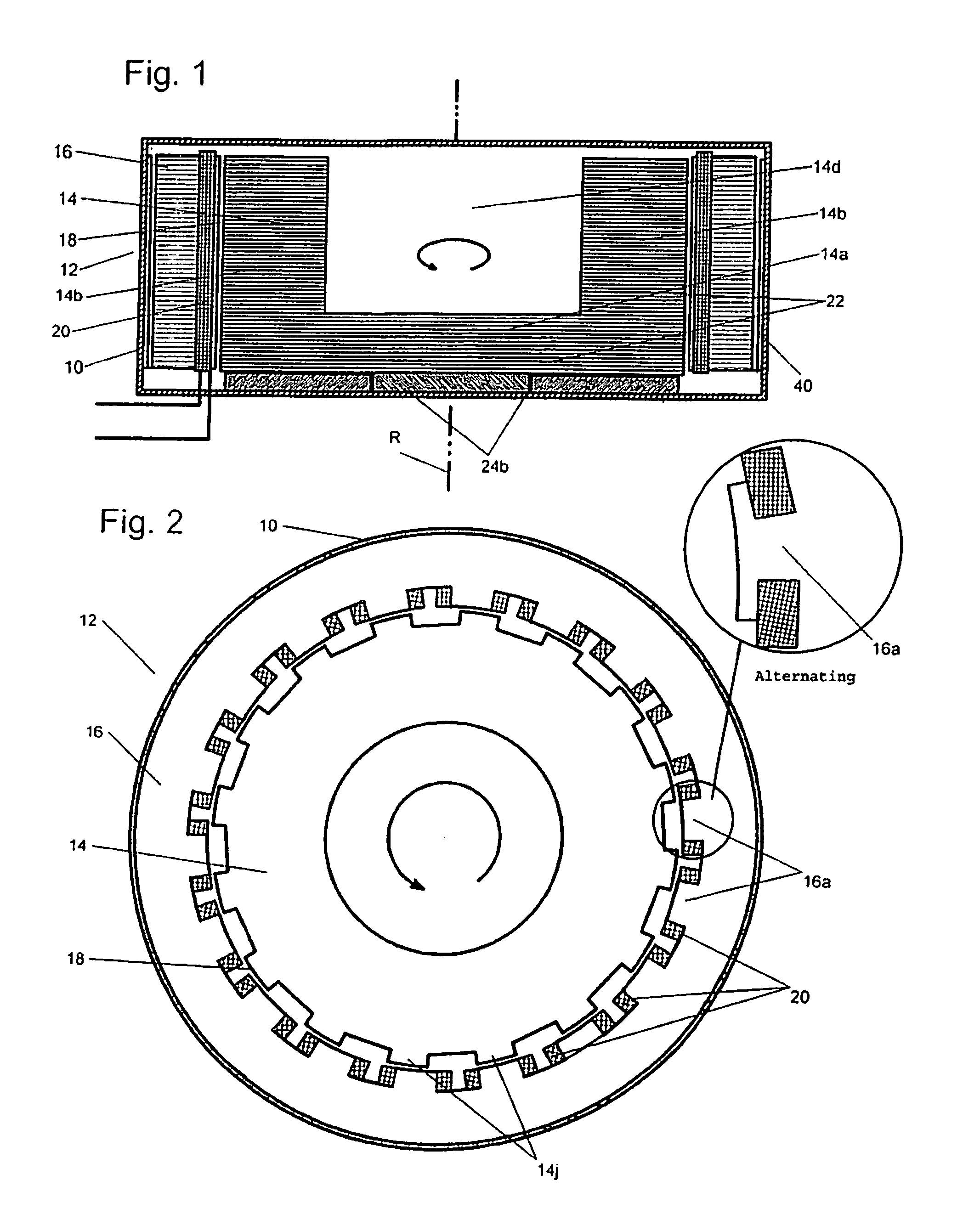
[0034]Shown in FIGS. 1 and 2 is an energy storage device that is arranged in a closed, circular-cylindrical, shear-resistant housing 10. Accommodated in the housing 10 is an electrical machine 12 in the form of a switched reluctance machine that comprises a rotor 14 and a stator 16. Details of the reluctance machine are explained further below. The stator 16 is separated from the rotor 14 by an air gap 18, and has a multiplicity of stator coils 20, which are assigned, respectively, to a stator tooth 16a. The rotor 14 is surrounded by the stator 16 and has a substantially pot-shaped form, having a base part 14a and a substantially annular-cylindrical wall part 14b. Further, assigned to the rotor 14 in a structurally integral manner is a fly-mass 22, which, together with the rotor 14, constitutes a rotating body. In the example shown, this fly-mass 22 is constituted in that the base part 14a and the annular-cylindrical wall part 14b are composed of significantly more material than wou...


PUM


Abstract

The energy storage device has an electrical machine (12) comprising a rotor (14) and a stator (16), the stator (16) being separated from the rotor (14) by an air gap (18) and having at least one stator coil (20). The rotor (14), moreover, has a fly-mass (22) and, together with the latter, constitutes a rotating body. The rotor (14) or the rotating body consists of a multiplicity of thin sheet-metallic discs (30), which have the form, substantially, of an annular disc having an outer edge and an inner edge. There has been applied to these sheet-metal discs (30), at their outer edge, a first tensile stress and, at their inner edge, a first shear stress.

Description

INTRODUCTION[0001]Described in the following is an energy storage device that is suitable, for example, for use in a land vehicle. This can be an energy storage device for vehicles that are equipped exclusively, or in addition to an internal combustion engine, with at least one electrical machine in the drive train. The described energy storage device is also suitable, however, for use in stationary or flying applications.BACKGROUND[0002]In the past, the electrical energy required in motor vehicles was, practically, produced entirely from fossil fuel (petrol, natural gas or diesel). In the case of electrically operated rail vehicles there is, for example, the concept whereby the kinetic energy released during braking is changed back into electrical (potential) energy—instead of being converted into frictional heat—and is fed back into the supply network. Now also in motor vehicles, by means of appropriate feedback control devices, during braking phases at least a portion of the brak...

Claims


Application Information

Patent Timeline
IPC IPC(8): H02K37/04H02K5/10
CPCH02K7/025Y02E60/16H02K19/103
Inventor GRUNDL, ANDREASHOFFMANN, BERNHARD
Owner COMPACT DYNAMICS
Why Eureka
Try Eureka