Control system of a power factor correction circuit

Active Publication Date: 2010-05-06
FUJI ELECTRIC CO LTD
View PDF6 Cites 27 Cited by
  • Summary
  • Abstract
  • Description
  • Claims
  • Application Information

AI Technical Summary

Benefits of technology

[0016]It is therefore an abject of the present invention to provide a control system of a power factor correction circuit that performs stabilized oscillat

Problems solved by technology

The conventional current control system as shown in FIG. 4 has problems that it requires two error amplifiers making the control circuit large sized and that it needs complicated adjustment of feedback constants.
The conventional peak current control system as shown in FIG. 5, although it requires one error amplifier maintaining the control circuit relatively small sized, has a problem that stable oscillation in

Method used


Image

  • Control system of a power factor correction circuit
  • Control system of a power factor correction circuit
  • Control system of a power factor correction circuit

Examples


Embodiment Construction

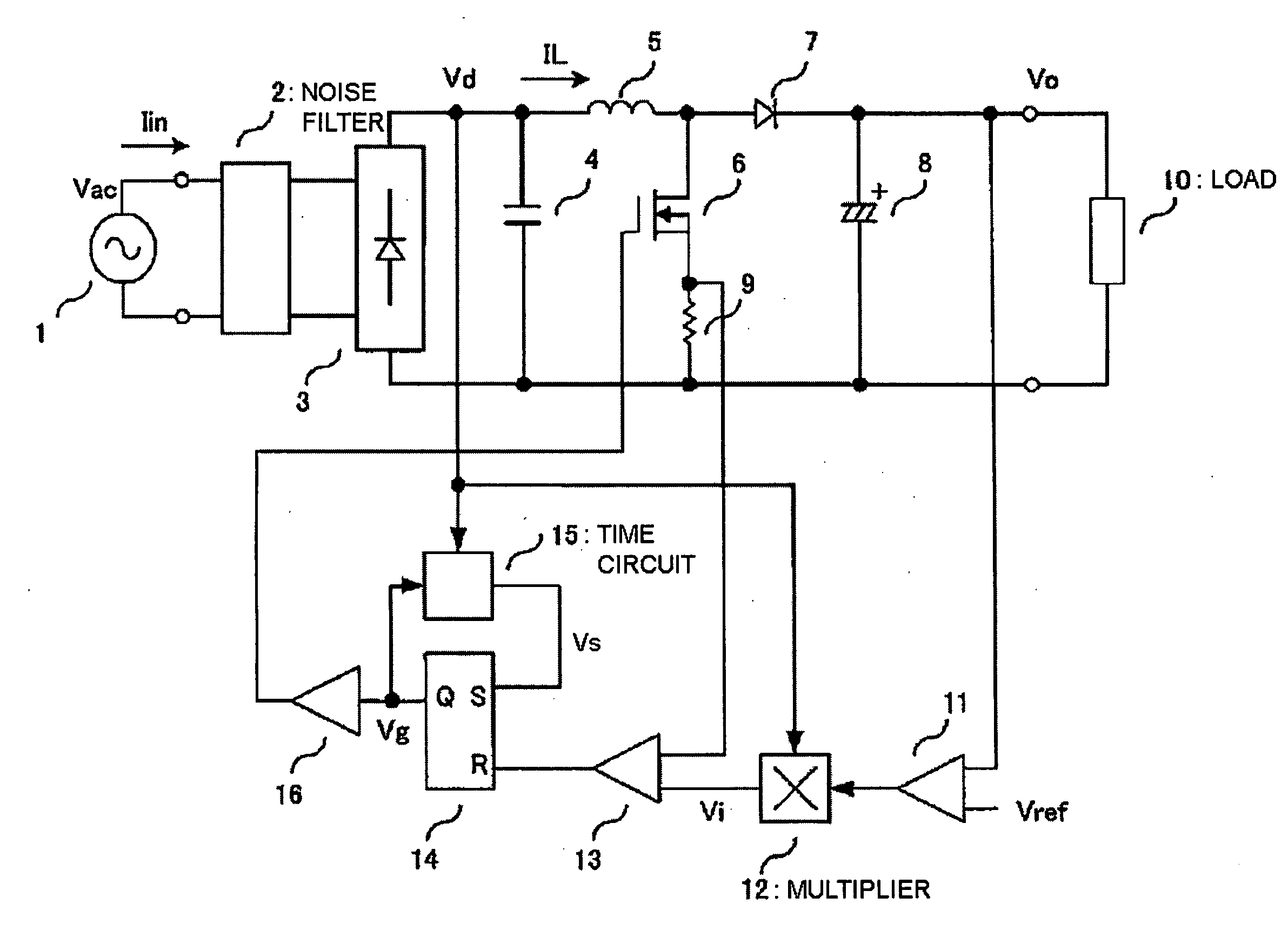
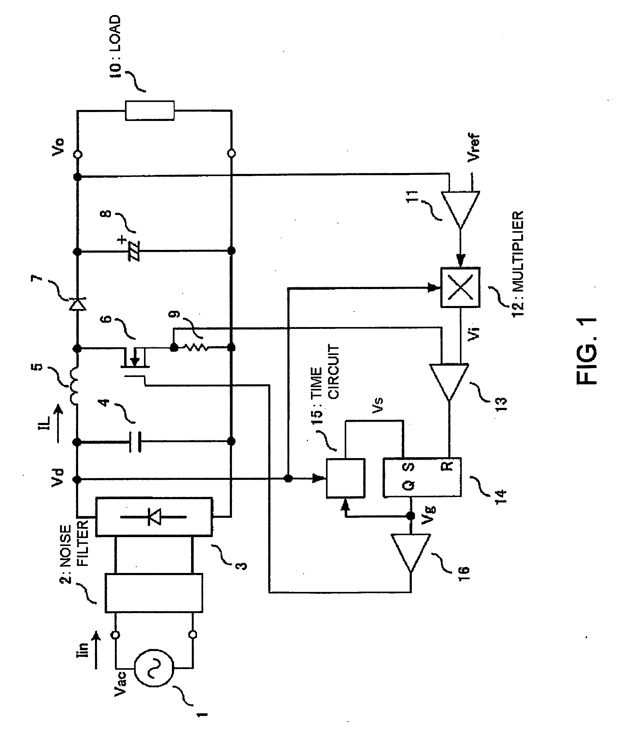
[0032]FIG. 1 shows a circuit construction of a control system of a power factor correction circuit of an embodiment according to the invention. Referring to FIG. 1, a main circuit of a switching regulator with power factor correction is composed of a noise filter 2, a rectifier bridge 3 for full-wave rectifying the voltage of an AC power source 1 input through the noise filter 2, and a booster circuit including an inductor 5, a switching element 6, a diode 7, and a smoothing capacitor 8, the booster circuit being connected to the output of the rectifier bridge 3. The capacitor 4 is provided for absorbing a switching noise due to switching of the switching element 6. The current detecting resistor 9 detects the current running in the switching element 6. The diode 7 can be replaced by a synchronous rectification transistor. In that case, the synchronous rectification transistor is turned on and off in complementary operation to the switching element 6.

[0033]In order to control the bo...


PUM


Abstract

A control system for a power factor correction circuit performs stabilized oscillation operation and suppresses switching frequency variation due to change of the AC power source. A control system includes a voltage error amplifier for outputting a voltage error signal obtained by amplifying a difference between a DC output voltage Vo and a command value Vref of the DC output voltage, a current command value generating circuit for outputting a current command value Vi for controlling the input current Iin, a comparator comparing an inductor current signal obtained by detecting an inductor current running in the switching element by a current detecting resistor with a magnitude of the output signal Vi from the multiplier, a timer circuit for setting an off-period of the switching element corresponding to the voltage Vd, and a reset-set type flip-flop circuit for setting an off-timing of the switching element after an elapse of the off-period.

Description

CROSS-REFERENCE TO RELATED APPLICATION[0001]This application is based on, and claims priority to, Japanese Patent Application No. 2008-284922, filed on Nov. 6, 2008, the entirety of which is incorporated herein by reference.BACKGROUND OF THE INVENTION[0002]1. Field of the Invention[0003]The present invention relates to a switching regulator for obtaining a stabilized DC output from an AC power source, in particular, to a control system of a power factor correction circuit for suppressing higher harmonic current flowing out to the AC power source side.[0004]2. Description of the Related Art[0005]In order to suppress higher harmonic current flowing out to the AC power source side, power factor correction circuits using a boosting chopper are widely applied to switching regulators, the boosting chopper comprising a rectifier bridge, an inductor, a switching element, a diode or a synchronous rectifier switching element, and a capacitor. Switching regulators in a several hundred watts cl...

Claims


Application Information

Patent Timeline
IPC IPC(8): H02M7/217
CPCH02M1/4225Y02B70/126Y02P80/112Y02B70/10Y02P80/10
Inventor NISHIKAWA, YUKIHIRO
Owner FUJI ELECTRIC CO LTD
Why Eureka
Try Eureka