Configurations And Methods For Carbon Dioxide And Hydrogen Production From Gasification Streams

a technology of gasification stream and carbon dioxide, which is applied in the direction of hydrogen separation using liquid contact, sulfur preparation/purification, separation process, etc., can solve the problems of high cost, high cost, and high cost of all or almost all of these processes, and achieve significant energy savings

Inactive Publication Date: 2010-05-06
FLUOR TECH CORP
View PDF27 Cites 48 Cited by
  • Summary
  • Abstract
  • Description
  • Claims
  • Application Information

AI Technical Summary

Benefits of technology

[0011]The present invention is directed to configurations and methods of treating syngas to remove acid gas, and especially to remove hydrogen sulfide and carbon dioxide. So treated syngas can then be used in various manners (e.g., combustion in IGCC power plant) and the carbon dioxide may be sequestered or liquefied for storage and / or transport. Most preferably, contemplated methods and plants have a desulfurization and decarbonization section in which separate absorbers absorb the acid gas components. Solvents are then regenerated in the respective sections by flashing and stripping, which provides significant energy savings.

Problems solved by technology

While such IGCC plants are reasonably efficient in upgrading low-grade carbonaceous products to generate electricity, significant carbon and sulfur emissions are often generated, particularly from the exhaust of the combustion gas turbines (e.g., sulfurous oxides, CO2, etc.).
However, all or almost all of these processes tend to be cost prohibitive and energy inefficient due to the operation at atmospheric pressure and the relatively low CO2 partial pressure in the gas turbine exhaust.
However, where stringent CO2 dioxide removal is required, membrane systems typically require multiple stages and recompression between the stages, which is often cost prohibitive.
However, chemical solvents generally require extensive heating and lean solvent cooling and often further require high solvent recirculation, which increases proportionally with the acid gas concentration in the syngas.
Therefore, such processes are suitable for treating unshifted syngas with low acid gas content but are problematic in treating shifted syngas that contains large amount of CO2 (e.g., greater than 30 vol %).
However, such solvent requires low temperature refrigeration for solvent cooling, which is energy intensive.
While use of physical solvents can significantly reduce the energy requirement, various difficulties still exist.
Among other things, CO2 and H2S removal are often inefficient and incomplete, failing to meet today's stringent emission requirements.
Moreover, where the acid gas is H2S, co-absorption of CO2 is very high, which is problematic for downstream sulfur plants.
Almost all solvent processes co-absorb significant quantities of CO2 in a CO2 rich environment (e.g., shifted syngas) and consequently reduce their sulfur absorption capacity, and require higher solvent circulation and regeneration duties while generating undesirable CO2 emissions.
Unfortunately, such configurations also produce an acid gas enriched in CO2 that is problematic for a downstream sulfur plant.
Consequently, although many configurations and methods for H2S and CO2 removal from syngas are known in the art, all or almost all of them suffer from various disadvantages.

Method used


Image

  • Configurations And Methods For Carbon Dioxide And Hydrogen Production From Gasification Streams
  • Configurations And Methods For Carbon Dioxide And Hydrogen Production From Gasification Streams
  • Configurations And Methods For Carbon Dioxide And Hydrogen Production From Gasification Streams

Examples


Embodiment Construction

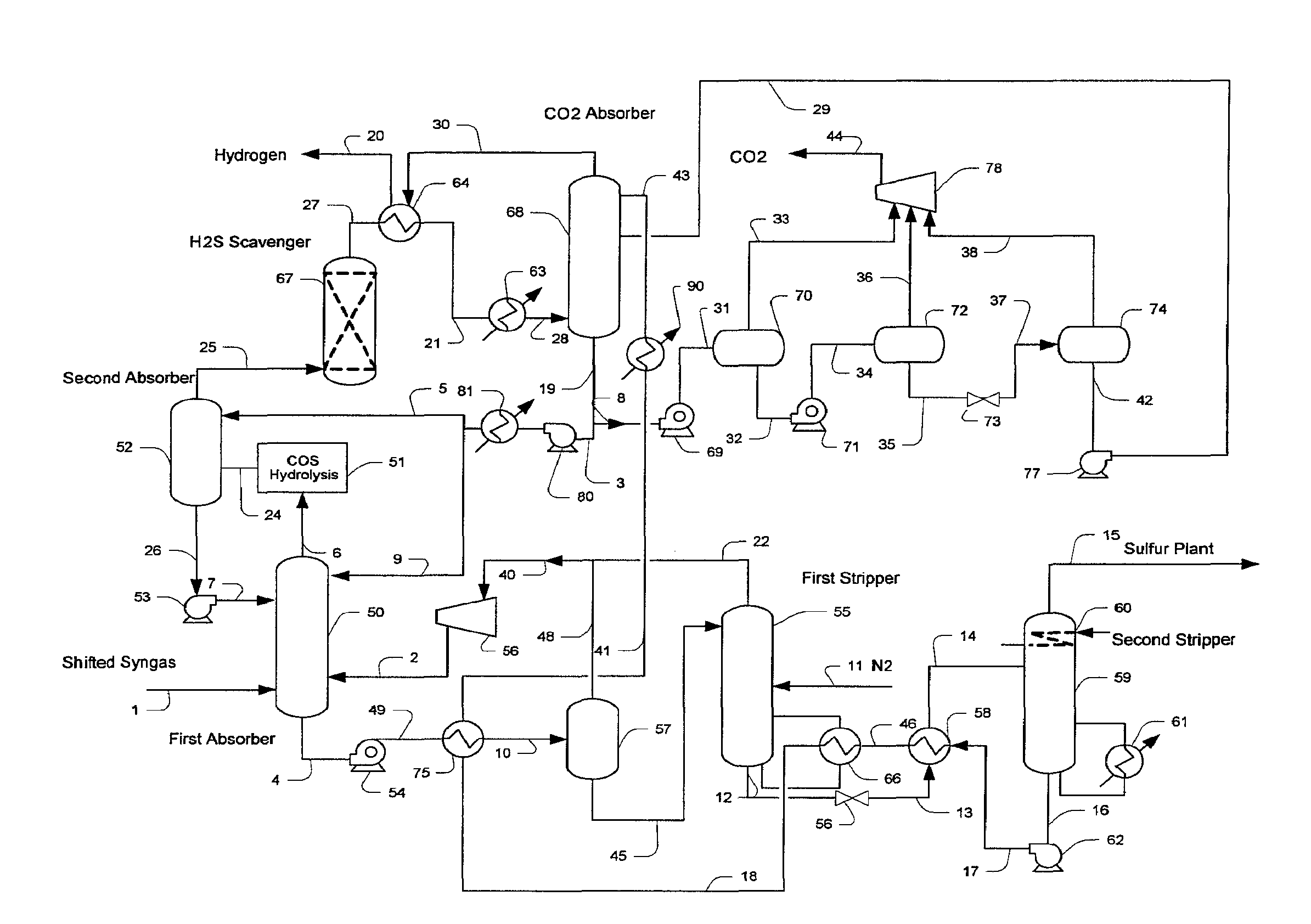
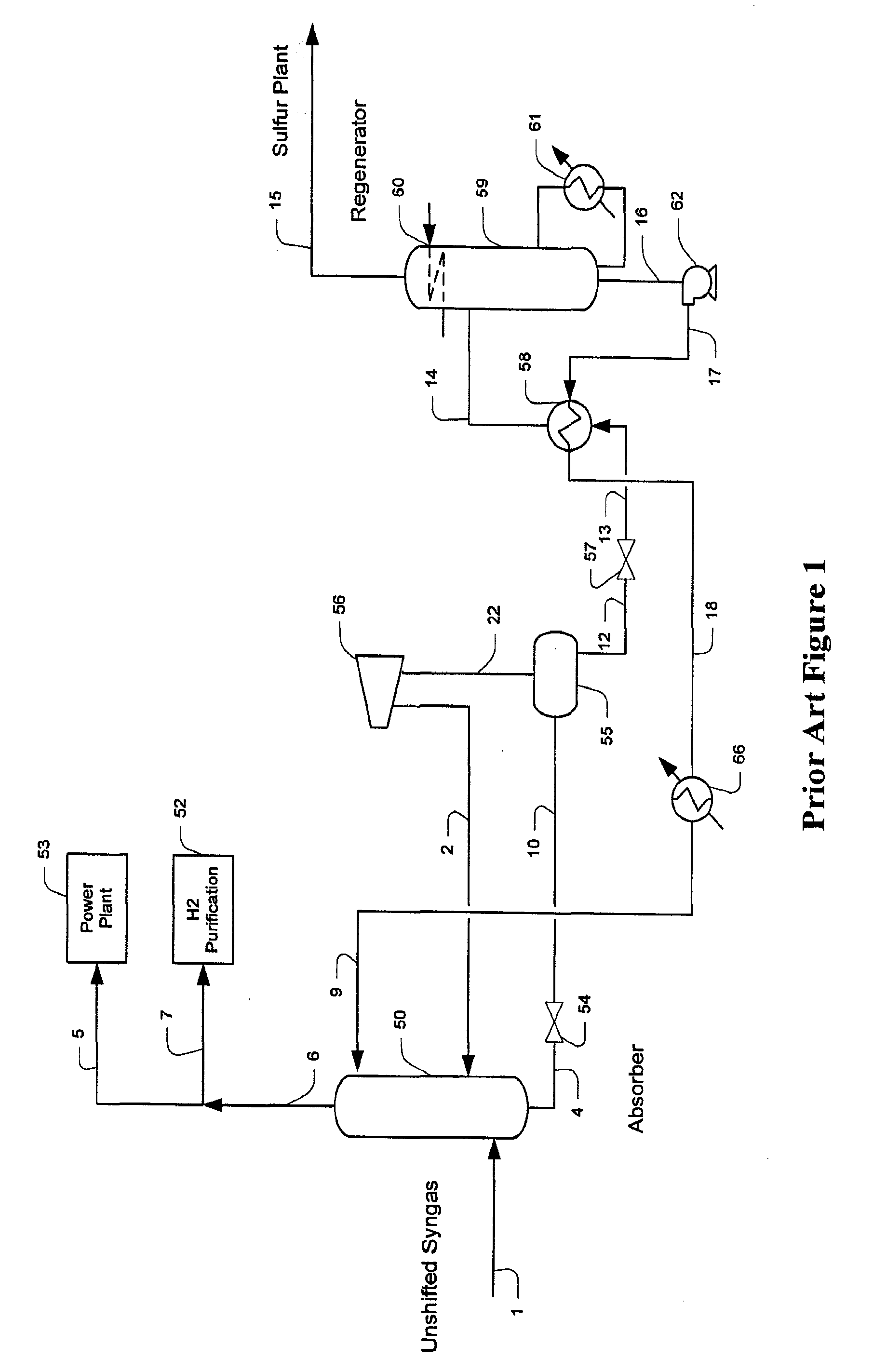
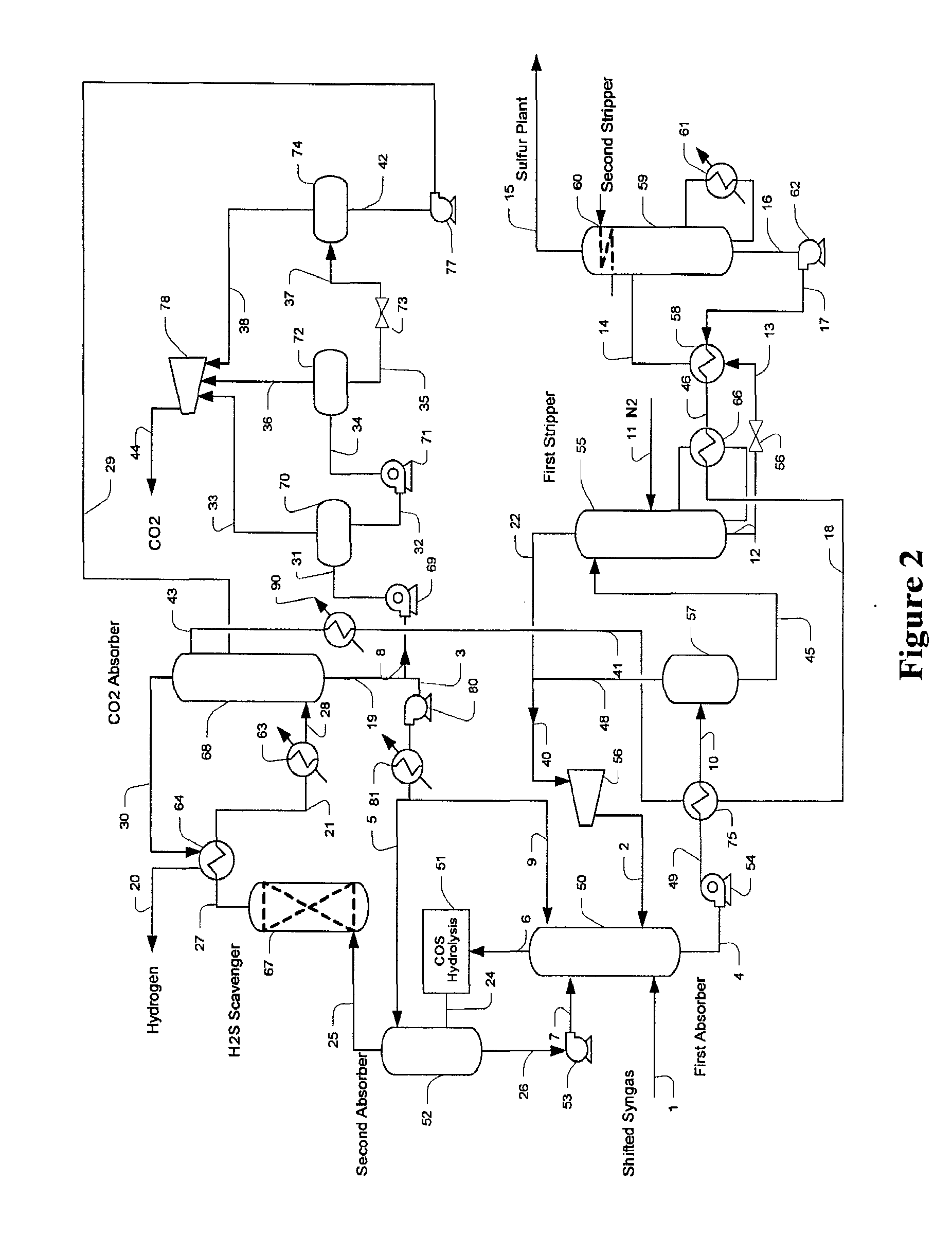
[0023]The present invention is directed to plant configurations and methods for treatment of syngas gas comprising H2, CO2, CO, H2S, and COS, in which hydrogen sulfide is removed in a first section, and in which carbon dioxide is removed in a second section. Contemplated sections include absorbers in which a single solvent or separate and distinct solvents are used to absorb the respective acid gas components. H2S rich solvent is preferably regenerated in one or more strippers using external heat, while CO2 rich solvent is preferably regenerated by flashing of the solvent to lower pressures. In especially preferred plants, H2S absorption is performed upstream of CO2 absorption.

[0024]Where the carbon dioxide concentration in the syngas is relatively low (e.g., unshifted syngas), the solvent circulation and the solvent type for the H2S and CO2 absorber sections may be separate and different. On the other hand, where the carbon dioxide concentration in the syngas is relatively high (e....


PUM

PropertyMeasurementUnit
temperatureaaaaaaaaaa
pressureaaaaaaaaaa

Abstract

A syngas treatment plant is configured to remove sulfurous compounds and carbon dioxide from shifted or un-shifted syngas in a configuration having a decarbonization section and a desulfurization section. Most preferably, the solvent in the decarbonization section is regenerated and cooled by flashing, while the solvent is regenerated in the desulfurization section via stripping using external heat, and it is still further preferred that carbonylsulfide is removed in the desulfurization section via hydrolysis, and that the so produced hydrogen sulfide is removed in a downstream absorber.

Description

[0001]This application claims priority to our copending U.S. provisional application with the Ser. No. 60 / 891,133, which was filed Feb. 22, 2007.FIELD OF THE INVENTION[0002]The field of the invention is hydrogen and carbon dioxide production from a syngas stream, and especially configurations and methods in which a sulfur scavenger and a solvent is employed to reduce carbon and sulfur emissions.BACKGROUND OF THE INVENTION[0003]Gasification of coal, residue oil, and other refinery waste is frequently integrated with combined-cycle power plants (IGCC) to produce additional electricity. The syngas from the gasification predominantly comprises H2, CO2, CO, H2S and COS is therefore often treated to remove sulfur where the syngas is used as fuel gas to the power plant. While such IGCC plants are reasonably efficient in upgrading low-grade carbonaceous products to generate electricity, significant carbon and sulfur emissions are often generated, particularly from the exhaust of the combust...

Claims


Application Information

Patent Timeline
Patent Type & Authority Applications(United States)
IPC IPC(8): C01B3/32C01B3/02B01D53/14C01B3/50C01B31/20C01B32/50
CPCB01D53/1406Y02P30/30B01D53/1475B01D2256/16B01D2257/304B01D2257/504C01B3/52C01B17/04C01B17/0456C01B17/164C01B31/20C01B2203/0415C01B2203/0475C01B2203/0485C01B2203/86Y02C10/04Y02C10/06Y02P20/152B01D53/1462C01B32/50Y02C20/40Y02P30/00Y02P20/151
Inventor MAK, JOHNNIELSEN, RICHARD
Owner FLUOR TECH CORP
Why Eureka
Try Eureka