
Drug delivery implants for inhibition of optical defects

a technology of optical defects and drug delivery, applied in the field of treatment of optical defects of the eye, can solve the problems of debilitating vision, eye optical defects that interfere with one's ability to see, and can range in severity,

Inactive Publication Date: 2010-05-06
MATI THERAPEUTICS
View PDF20 Cites 142 Cited by
  • Summary
  • Abstract
  • Description
  • Claims
  • Application Information

AI Technical Summary

Benefits of technology

[0010]In many embodiments, a retention element can be attached to the structure to retain the structure along a natural tissue surface of or adjacent to the eye. The retention element can be shaped to retain the structure in or adjacent at least one of a punctual duct, a scleral tissue, or a conjunctival tissue. The structure can be shaped to retain the structure adjacent at least one of a punctual duct, a scleral tissue, or a conjunctival tissue. The structure may have at least one surface and release a therapeutic quantity of the therapeutic agent into tear or tear film fluid of the eye throughout a time period of at least one week when the implant is implanted with the at least one surface exposed to the tear or tear film fluid. For example, the structure can be adapted to release the therapeutic agent in therapeutic amounts over a period of time from about one to twelve months after the structure is inserted into the eye, and the structure may comprise at least one of a reservoir, a matrix, a solution, a surface coating or a bioerodable material. The structure may comprise a drug core and a layer disposed over the drug core to inhibit release of the therapeutic agent through the layer, and the layer may comprise an opening formed therein to release the drug through the opening. The structure may comprise particles of the agent, and the particles may independently release the agent therefrom when the structure is implanted to provide a substantially uniform release rate.

Problems solved by technology

Pathological conditions that degrade vision can be debilitating.
Optical defects of the eye that interfere with one's ability to see can range in severity from nearly imperceptible to blindness.
One common form of optical defect of the eye is refractive error of the eye, with typical refractive errors including nearsightedness or myopia, farsightedness or hyperopia, and astigmatism.
Refractive error of the eye generally results from imperfection in the physical properties of the ocular tissues of the eye so that an image formed on the retina is less than ideal.
Imperfections in either the cornea or the crystalline lens can result in refractive error of the eye.
The positions of the cornea and crystalline lens in relation to each other and in relation to the retina can also effect image quality and refractive error.
For example, if the distance from the crystalline lens to the retina is too long, a patient can suffer from myopia.
Although these treatments are generally effective, each treatment modality has limitations and may not be suitable for everyone.
For example, eyeglasses and contact lenses are not a permanent form of correction and are only effective while worn.
Thus, many people suffer from significant degradation in their vision when these lenses are not worn.
Intraocular lenses are invasive and require surgery, so that the use of intraocular lenses is often limited to the treatment of cataracts.
Although laser eye surgery is effective this elective surgery can occasionally result in complications, so that many people choose to live the inconvenience and limitations of eyeglasses and / or contact lenses.
In addition to the above limitations, these therapies generally attempt to correct optical defects of an eye after the defect has developed.
However, the application of liquid drops with atropine can result in side effects and may involve applying liquid drops regularly for an extended time.
In addition, the eye drop format can be difficult to instill in children making compliance a significant issue in treatment.
As such, since compliance to the drop regimen may be determinative to the desired clinical outcome, missing doses can lead to further disease progression.

Method used


Image

  • Drug delivery implants for inhibition of optical defects
  • Drug delivery implants for inhibition of optical defects
  • Drug delivery implants for inhibition of optical defects

Examples


Embodiment Construction

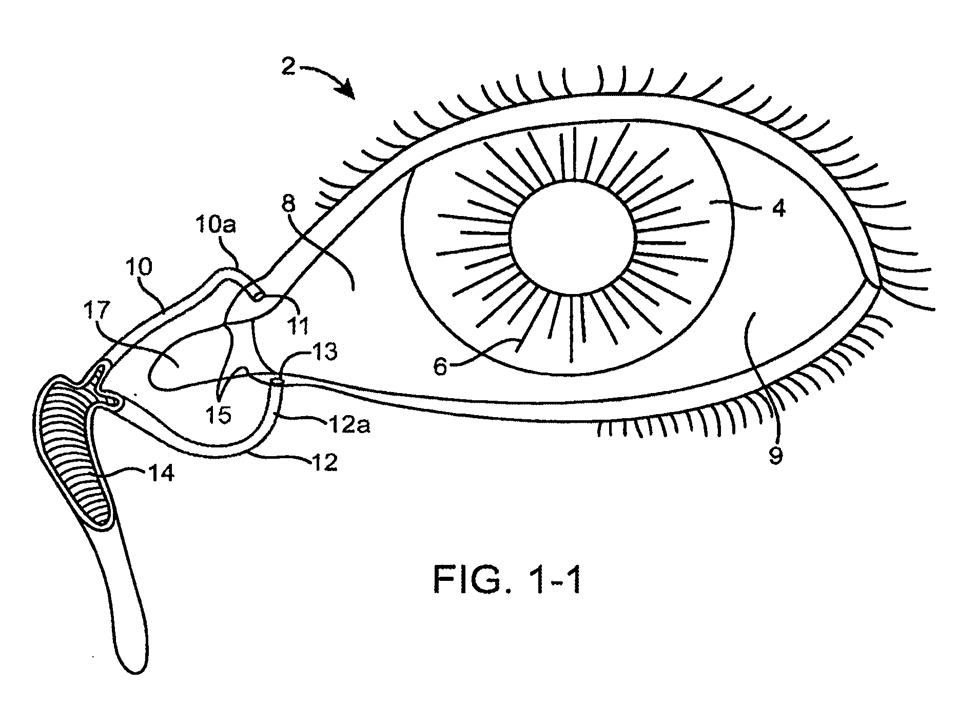
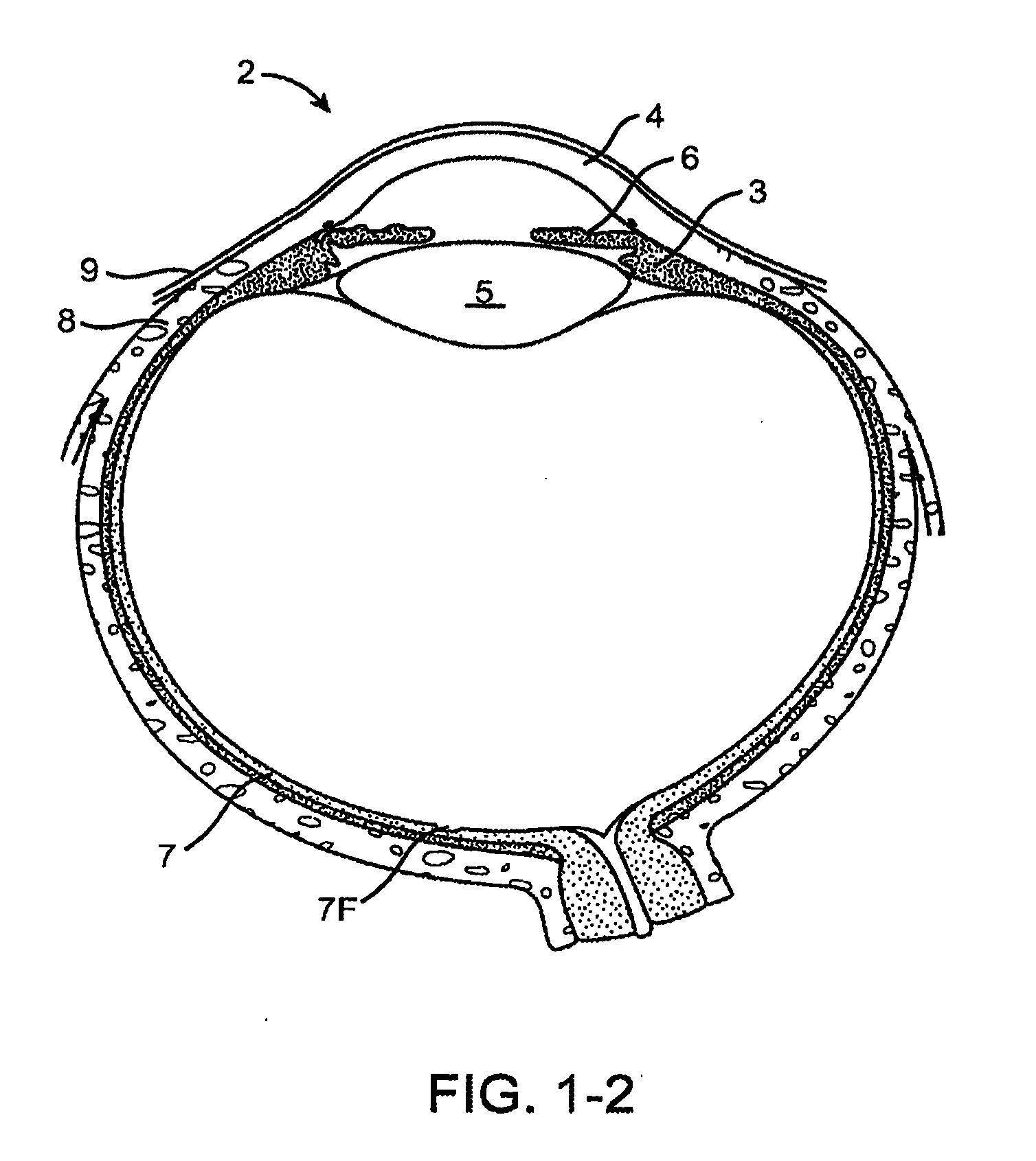
[0051]FIGS. 1-1 and 1-2 show anatomical tissue structures of an eye 2 suitable for treatment with implants, according to an embodiment of the present invention. Eye 2 includes a cornea 4 and an iris 6. A sclera 8 surrounds cornea 4 and iris 6 and appears white. A conjunctival layer 9 is substantially transparent and disposed over sclera 8. A crystalline lens 5 is located within the eye. A retina 7 is located near the back of eye 2 and is generally sensitive to light. Retina 7 includes a fovea 7F that provides high visual acuity and color vision. Cornea 4 and lens 5 refract light to form an image on fovea 7F and retina 7. The optical power of cornea 4 and lens 5 contribute to the formation of images on fovea 7F and retina 7. The relative locations of cornea 4, lens 5 and fovea 7F are also important to image quality. For example, if the axial length of eye 2 from cornea 4 to retina 7F is large, eye 2 can be myopic. Also, during accommodation, lens 5 moves toward cornea 4 to provide go...


PUM


Abstract

An implant for use with an eye comprises an implantable structure and a therapeutic agent. The therapeutic agent is deliverable from the structure into the eye so as to therapeutically effect and / or stabilize a refractive property of the eye. In many embodiments, the refractive property of the eye may comprise at least one of myopia, hyperopia or astigmatism. The therapeutic agent can comprise a composition that therapeutically effects or stabilizes the refractive property of the eye. The therapeutic agent may comprise at least one of a mydriatic or a cycloplegic drug. For example, the therapeutic agent may include a cycloplegic that comprises at least one of atropine, cyclopentolate, succinylcholine, homatropine, scopolamine, or tropicamide. In many embodiments, a retention element can be attached to the structure to retain the structure along a natural tissue surface.

Description

CROSS-REFERENCES TO RELATED APPLICATIONS[0001]This application claims the benefit of under 35 U.S.C. §109(e) of U.S. Provisional Patent Application No. 60 / 871,867 filed on Dec. 26, 2007, the disclosure of which is incorporated herein by reference.BACKGROUND OF THE INVENTION[0002]The present invention is directed to the treatment of optical defects of the eye with implants that release one or more therapeutic agents.[0003]Pathological conditions that degrade vision can be debilitating. Optical defects of the eye that interfere with one's ability to see can range in severity from nearly imperceptible to blindness. One common form of optical defect of the eye is refractive error of the eye, with typical refractive errors including nearsightedness or myopia, farsightedness or hyperopia, and astigmatism. Refractive error of the eye generally results from imperfection in the physical properties of the ocular tissues of the eye so that an image formed on the retina is less than ideal. The ...

Claims


Application Information

Patent Timeline
IPC IPC(8): A61F2/16
CPCA61F9/0017A61K9/0051A61F9/00781A61F9/00772A61P27/02A61M31/00A61F2/142A61M35/00A61P27/10A61P27/06A61P27/04A61P27/08
Inventor DE JUAN, JR., EUGENEREICH, CARY J.BOYD, STEPHENGIFFORD, HANSON S.DEEM, MARK
Owner MATI THERAPEUTICS
Learn More