Manufacturing method for a thermal head

Inactive Publication Date: 2010-05-13
SEIKO INSTR INC
View PDF3 Cites 2 Cited by
  • Summary
  • Abstract
  • Description
  • Claims
  • Application Information

AI Technical Summary

Benefits of technology

[0007]The present invention has been made in view of the above-mentioned circumstances, and an object of the present invention is therefore to provide a manufacturing method for a thermal head, which enables to manufacture a thermal head having high heating efficiency and stable quality.

Problems solved by technology

In this manufacturing method, there is a risk that the substrate breaks because the hollow portion is formed before the substrate is reinforced by the supporting plate, and there is a problem that it is difficult to handle the substrate during a manufacturing process.
Further, an original thickness of each of the substrates varies, and hence there is a problem that it is difficult to control the thickness of the substrate serving as the heat storage layer above the hollow portion.

Method used


Image

  • Manufacturing method for a thermal head
  • Manufacturing method for a thermal head
  • Manufacturing method for a thermal head

Examples


first embodiment

[0041]Hereinafter, with reference to the drawings, a manufacturing method A for a thermal head according to a first embodiment of the present invention is described.

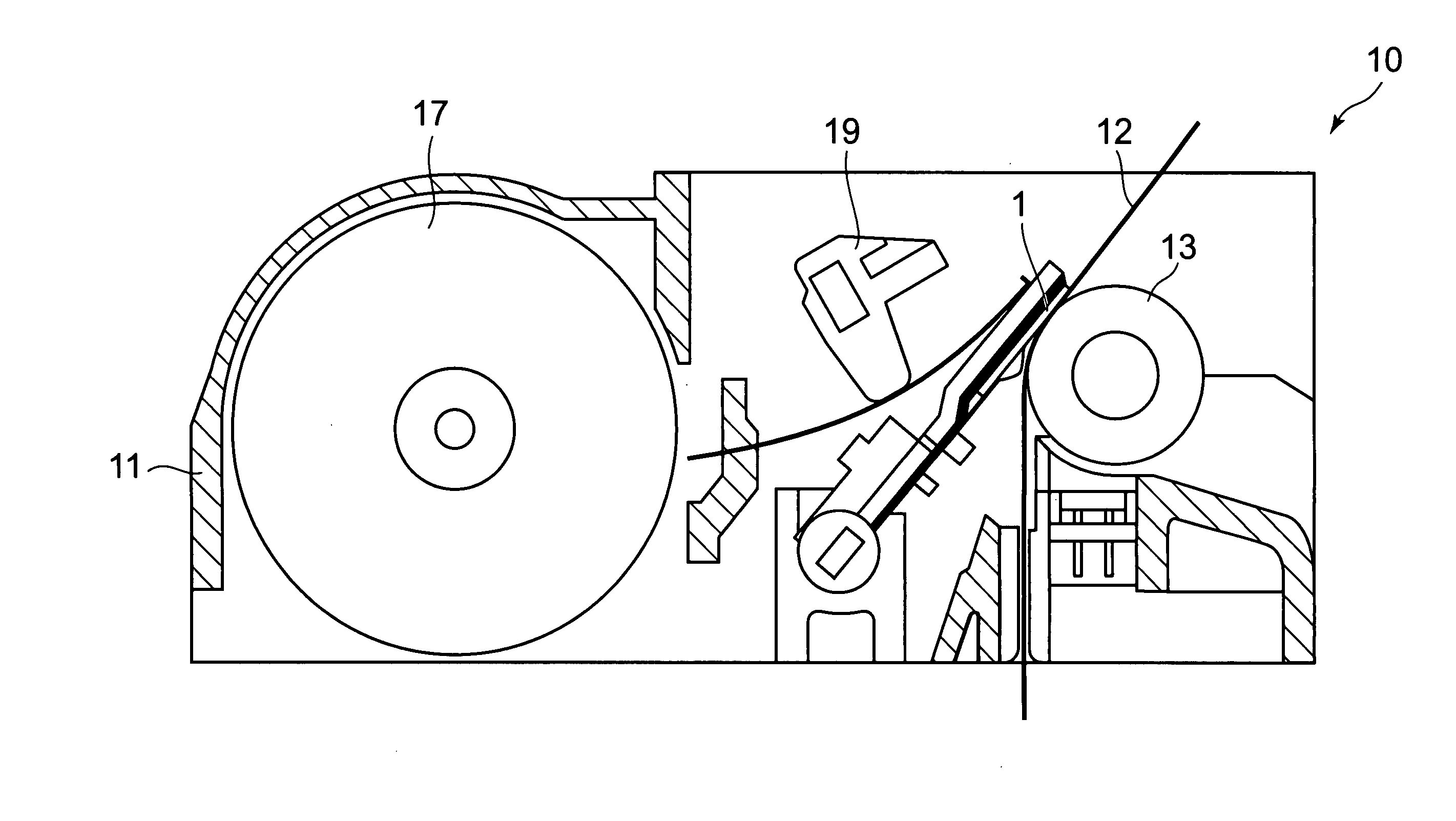
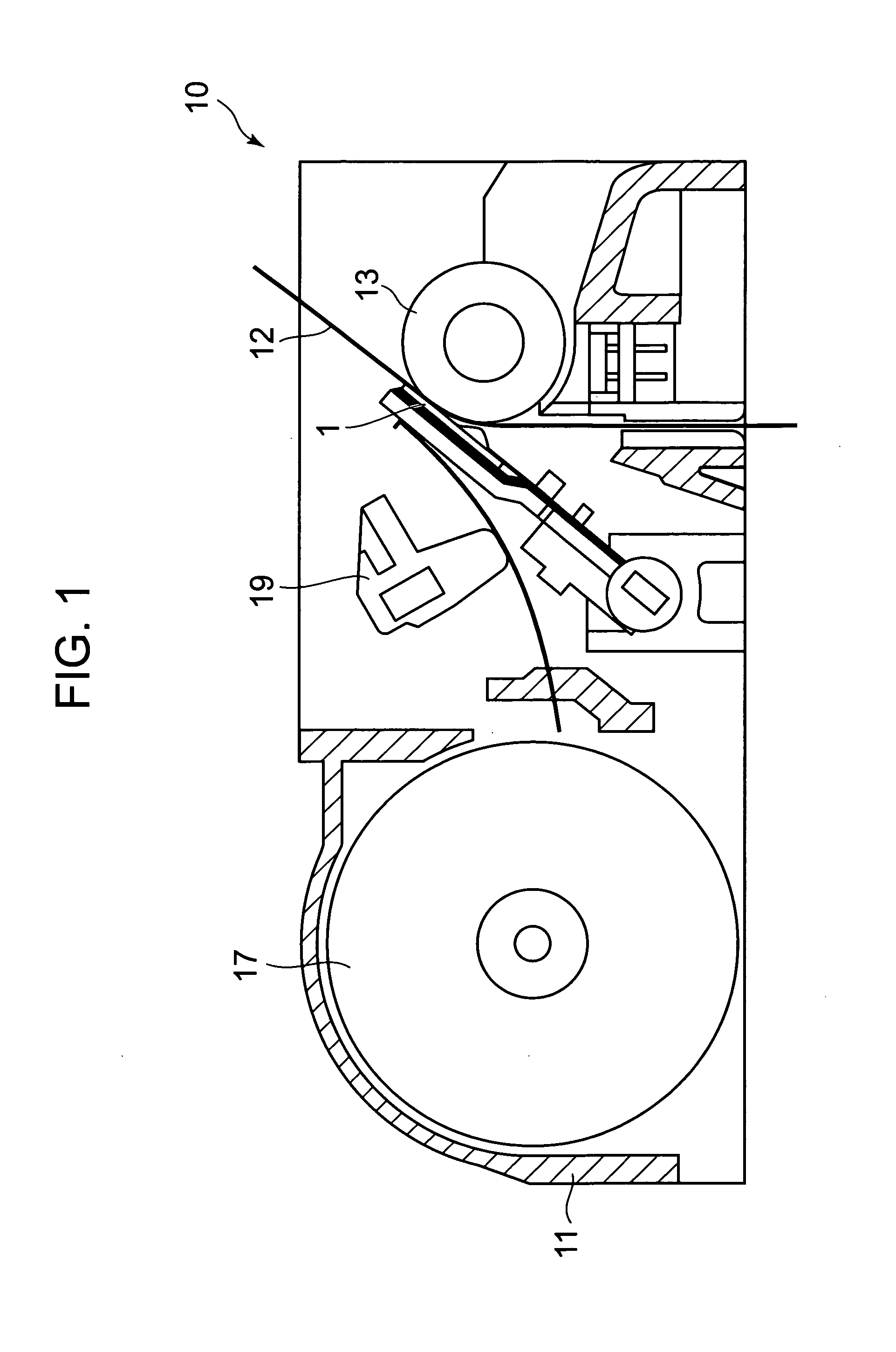
[0042]The manufacturing method A for a thermal head according to this embodiment is a manufacturing method, for example, for a thermal head 1 used in a thermal printer 10 illustrated in FIG. 1.

[0043]The thermal printer 10 includes: a main body frame 11; a platen roller 13 arranged horizontally; the thermal head 1 arranged so as to be opposed to the outer peripheral surface of the platen roller 13; a heat dissipation plate 15 (see FIG. 2) supporting the thermal head 1; a paper feeding mechanism 17 for feeding an object to be printed such as thermal paper 12 between the platen roller 13 and the thermal head 1; and a pressure mechanism 19 for pressing the thermal head 1 with a predetermined pressing force with respect to the thermal paper 12.

[0044]Against the platen roller 13, the thermal head 1 and the thermal paper 12 are...

second embodiment

[0077]Hereinafter, a manufacturing method B of the thermal head 1 according to a second embodiment of the present invention (hereinafter, simply referred to as “manufacturing method B”) is described with reference to a flowchart of FIG. 12.

[0078]The manufacturing method B according to this embodiment is different from the manufacturing method A according to the first embodiment in that, in the concave portion forming step, the hollow concave portions 2 and the marking concave portions 6 are formed by hot pressing, instead of the etching with use of the barrier films 21.

[0079]Hereinafter, in the description of this embodiment, portions having the common structures with those in the manufacturing method A for the thermal head 1 according to the first embodiment are denoted by the same reference symbols, and description thereof is omitted.

[0080]In the concave portion forming step, as illustrated in FIG. 13, the hot pressing is performed in a region of the one surface 50A of the thin pl...


PUM

PropertyMeasurementUnit
Thicknessaaaaaaaaaa
Efficiencyaaaaaaaaaa

Abstract

Provided is a manufacturing method for a thermal head, which enables to manufacture a thermal head having high heating efficiency and stable quality. The manufacturing method for a thermal head includes: a concave portion forming step of forming a hollow concave portion and a marking concave portion having a depth larger than a depth of the hollow concave portion on one surface of a thin plate glass; a bonding step of bonding a supporting plate onto the one surface of the thin plate glass, in which the hollow concave portion and the marking concave portion are formed in the concave portion forming step; a thinning step of thinning the thin plate glass onto which the supporting plate is bonded in the bonding step until the marking concave portion extends through the substrate from a side of a back surface opposite to the one surface; and a heating resistor forming step of forming a heating resistor on the back surface of the thin plate glass thinned in the thinning step so as to be opposed to the hollow concave portion.

Description

BACKGROUND OF THE INVENTION[0001]1. Field of the Invention[0002]The present invention relates to a manufacturing method for a thermal head.[0003]2. Description of the Related Art[0004]There have been conventionally known a thermal head which is used in a thermal printer often mounted to a portable information equipment terminal typified by a compact hand-held terminal, and which is used to perform printing on a thermal recording medium based on printing data with the aid of selective driving of a plurality of heating elements (for example, see JP 2007-320197 A).[0005]In terms of an increase in efficiency of the thermal head, there is a method of forming a heat insulating layer below a heating portion of a heating resistor. By formation of the heat insulating layer below the heating portion, of an amount of heat generated on the heating resistor, an amount of upper-transferred heat which is transferred to an abrasion resistance layer formed above the heating portion becomes larger th...

Claims


Application Information

Patent Timeline
IPC IPC(8): H01C17/00
CPCB41J2/3359H01C1/148H01C7/003H01C17/065Y10T29/49204Y10T29/49083Y10T29/49087Y10T29/49146Y10T29/49099
Inventor SHOJI, NORIYOSHISANBONGI, NORIMITSUSATO, YOSHINORIMOROOKA, TOSHIMITSUKOROISHI, KEITARO
Owner SEIKO INSTR INC
Why Eureka
Try Eureka