
Moisture impermeable fire-barriers

a fire-barrier and moisture-impermeable technology, applied in the field of fire-barriers, can solve the problems of affecting the service life of workers, and presenting a major fire risk to the structure, and it is difficult if not impossible to prevent moisture from reaching the barrier

Inactive Publication Date: 2010-05-13
INPRO CORP
View PDF32 Cites 14 Cited by
  • Summary
  • Abstract
  • Description
  • Claims
  • Application Information

AI Technical Summary

Benefits of technology

"The present invention addresses the problem of moisture reaching fire-barriers and causing damage or impairing their effectiveness. The invention provides a solution by manufacturing fire-barriers that are both gas and water impermeable, meaning they are fully protected from moisture and water damage. The barriers can be installed in various ways, such as underground, within building units, or over the top, sides, or bottom. The barriers are tested and certified, and can be installed without any alterations required. Overall, the invention ensures the safety and integrity of fire-barriers for the life of the barrier."

Problems solved by technology

While expansion-joint spaces improve the life-time integrity of the structure, they also present a major fire risk to the structure.
When fire-barriers fail, loss of both life and property can be the result.
Even though a barrier cover plate and a fire-barrier are correctly installed into an expansion joint space, the present inventor realized that it is difficult if not impossible, to prevent moisture from reaching barriers.
For example, fire-barriers, especially those installed between adjacent floor units, are subjected to daily stress from exposure to moisture, especially from water and cleaning chemicals used for floor washing that can leak through the smallest of openings even when a boot has been installed.
Heavy rain combined with strong wind can provide for water to permeate even very small openings in the sides of buildings, causing wetting of the sides and bottoms of barriers.
The Inventor realized that water from repeated condensation events can impair or destroy the effectiveness of a barrier.
Public facilities, such as open stadiums are regularly subjected to the effects of rain and snow.
Fire-barrier failure in any of these facilities is likely to result in unnecessary hazard to life and to the facility.
And now that life-saving sprinkler systems are becoming more and more required, fire-barriers are subject to water damage from fire sprinkler water that is released during isolated fire events.
As mentioned above, repeated exposure to moisture results in deterioration of the barrier.
Furthermore, the presence of the cover presents a problem.
However, currently manufactured building units are frequently constructed from pre-cast concrete slabs that are only 4½ inches thick, leaving only ½ inch of space for the installation of a fire-barrier into expansion spaces between floor units.
Moreover, it is imperative that the boot does not protrude above the floor surface, as it would not only create a tripping hazard, it would additionally expose itself to damage.
If the boots are damaged by, for example, machines that are used to wash, maintain, or repair a floor, it is likely that moisture will reach the barriers.
Additionally, the weight of water collecting on the surface of a barrier creates added weight stress on the barrier and on the means used to attach the barrier to the building structures, in addition to weakening the barrier from, for example, the growth of mold and mildew on the damp materials.
The increase in a barrier's weight due to the presence of moisture or water greatly increases its weight, thus, compromises the integrity of the attachments and of the barrier.
Failed barriers, regardless of the reason for the failure, pose life-threatening consequences.
However, because of the weight of the barriers and the difficulty in handling very long barriers, the length of the barriers is usually limited to, for example, 10 feet.

Method used


Image

  • Moisture impermeable fire-barriers
  • Moisture impermeable fire-barriers
  • Moisture impermeable fire-barriers

Examples


Embodiment Construction

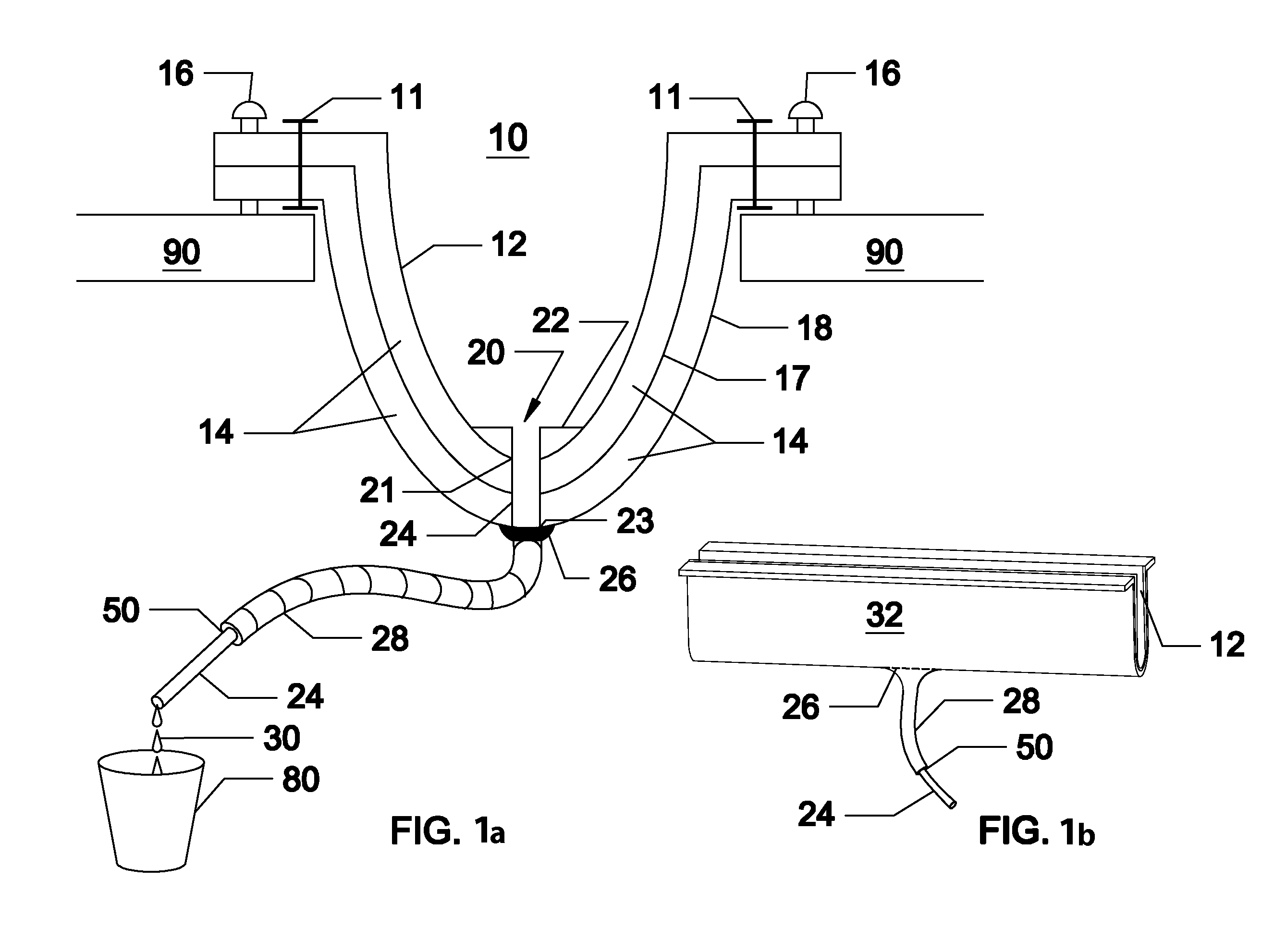
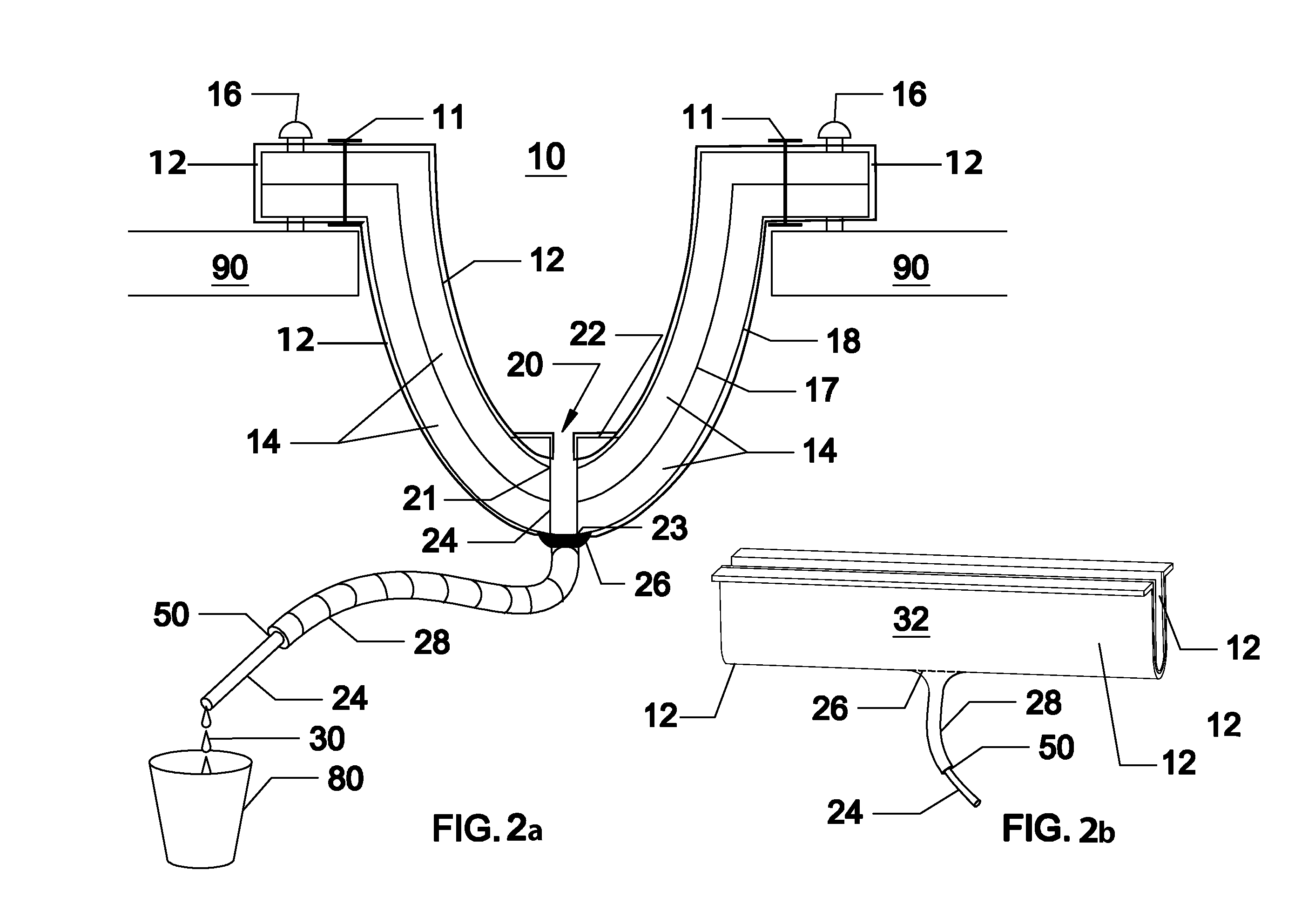
[0095]To provide an understanding of the basic structure of the moisture and gas impermeable barriers contemplated herein, we now refer to the drawings to illustrate exemplary versions of the invention. It should be noted that the disclosed invention is disposed to versions in various sizes, such as shapes, lengths, widths, and thicknesses, as well as to the one or many the multi-directional, multi-dimensional body sections to accommodate the large variety of expansion-joint spaces that require fire-barriers, in addition to variation in shapes, contents, number and composition of layers, materials, and attachment means. Therefore, the versions described herein are provided with the understanding that the present disclosure is intended as illustrative and is not intended to limit the invention to the versions described.

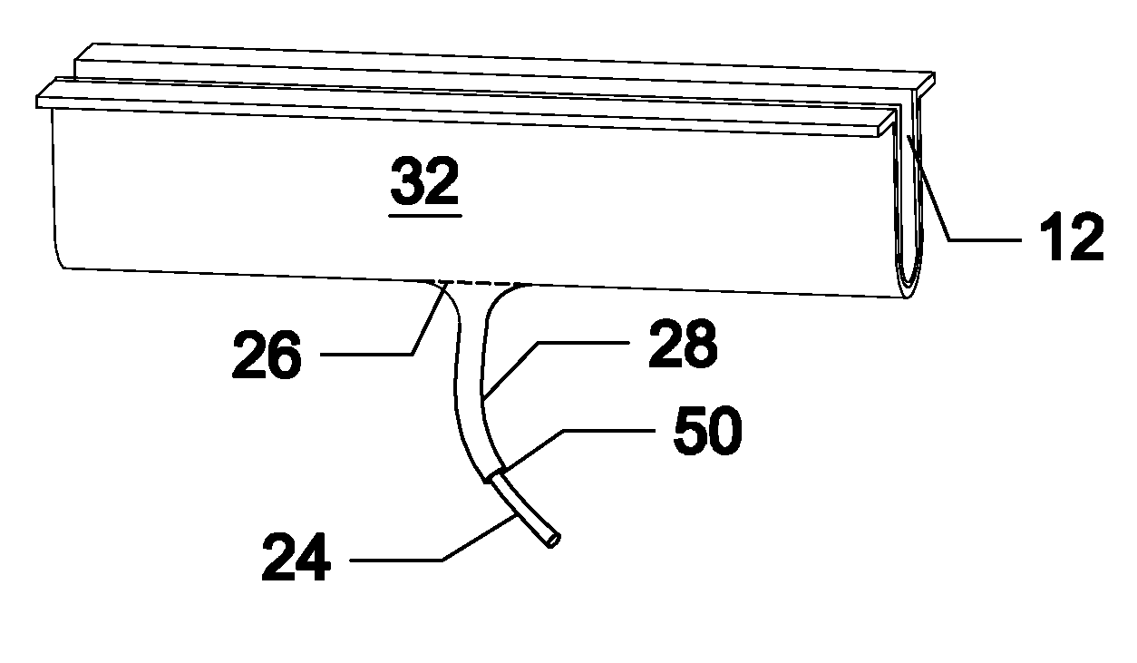
[0096]FIG. 1a is a cross-sectional diagrammatic view of a straight-line top-mount moisture-impermeable fire-barrier of the present invention installed in an expansion-...


PUM

PropertyMeasurementUnit
thickaaaaaaaaaa
lengthaaaaaaaaaa
ninety degree angleaaaaaaaaaa

Abstract

A preferred example of a pre-assembled, moisture, water, and gas impermeable fire-barrier system for use in expansion-joint spaces includes a fire-barrier having a first multi-layer of outermost protective cloth layer overlain by an insulation blanket overlain by stainless steel foil, a second multi-layer, overlaying and fixedly attached to the first multi-layer, containing an insulation blanket, overlain by a limited layer of intumescent material, overlain by impermeable silicon cloth to completely or partially surround the barrier, and a first attachment apparatus for attaching a first long edge of the fire-barrier to a building unit and a second attachment apparatus for attaching the opposing second long edge to an opposing spaced building unit, which attachment apparatus may be fixedly attached to the barrier, and where the barrier system may be fitted with a drain aperture and a drainage hose emanating from the aperture, the hose protected from the heat of a fire.

Description

CROSS-REFERENCE TO RELATED APPLICATIONS[0001]This Continuation-in-Part application claims benefit to Non-Provisional Patent application Ser. No. 12 / 185,160 filed Aug. 4, 2008 and to Provisional Application No. 60 / 953,703 filed Aug. 3, 2007.STATEMENT REGARDING FEDERALLY SPONSORED RESEARCH OR DEVELOPMENT[0002]Not ApplicableREFERENCE TO SEQUENCE LISTING, A TABLE OR A COMPUTER PROGRAM LISTING COMPACT DISK APPENDIX[0003]Not ApplicableBACKGROUND OF THE INVENTION[0004]The present invention relates generally to fire-barriers and more particularly to moisture impermeable fire-barriers.[0005]The background information discussed below is presented to better illustrate the novelty and usefulness of the present invention. This background information is not admitted prior art.[0006]Modern building codes require that stresses experienced by buildings from extreme and / or repetitive changes in temperature, the force of high winds impinging on the building, multi-directional forces due to seismic eve...

Claims


Application Information

Patent Timeline
Patent Type & Authority Applications(United States)
IPC IPC(8): E04B1/94E04B1/68E04B1/66E04B1/92
CPCE04B1/948
Inventor SHAW, ALAN
Owner INPRO CORP
Learn More