Optical and infrared periscope with display monitor

a periscope and display monitor technology, applied in the field of optical image forming apparatus, can solve the problems of lens switching system that requires additional manpower, periscope configurations have very limited image production and night time viewing capabilities, etc., and achieve the effect of cost-effective production and easy manufacturing

Inactive Publication Date: 2011-02-01
SEILER INSTR & MFG
View PDF14 Cites 4 Cited by
  • Summary
  • Abstract
  • Description
  • Claims
  • Application Information

AI Technical Summary

Benefits of technology

[0007]It is an object of the present invention to provide a periscope that is easy to manufacture and cost effective to produce.
[0009]It is another object of the present invention to provide a periscope where optical viewing may be achieved by one or many users.
[0010]It is still another object of the present invention to provide a periscope with a housing that is capable of containing all the advanced circuitry needed, and a housing that will not capture too much space, thus providing the viewer ample room to move.
[0012]The present invention includes a periscope that allows for better day and night time viewing. In the present invention, visual imaging is dramatically improved through utilization of two specialized cameras; one particularly suited for day time viewing, the bullet camera, and one specially adapted for low light viewing, the night board camera. In addition, the periscope of the present invention utilizes an 18 mm image intensifier tube, which up until now, has never been used in periscopes. Generally, ANVIS, aviator's night vision imaging system, are primarily used in conjunction with goggles. The 18 mm image intensifier tube provides the present invention with the capability of detecting and amplifying low light level images during night time viewing and surveillance, under moonlight or starlight. In addition, for very low light levels the 18 mm image intensifier may be equipped with two or three microchannel plates to create an image by detecting single photons. Furthermore, one may implement a high speed gate with the 18 mm image intensifier tube to capture a fast event such as motion analysis of high speed moving objects and fluorescence lifetime imaging. The viewing panel of the present invention is a high resolution flat panel display, which has electronic reticles that are in focus at all ranges. The flat panel viewing screen is also fatigue free, which results in improved gunner performance. The present invention also implements cutting edge circuitry which maintains proper LCD and camera operation at temperatures at or below 32° Fahrenheit. The advanced circuitry compares on board temperatures to ambient temperatures, and when the temperature falls below a predetermined threshold temperature, small amounts of current are allowed to flow to around the optical viewing equipment. In addition, unlike previous periscopes, the present invention allows for viewing of the optical display via a state of the art flat panel screen, which as mentioned previously has electronically generated reticles always in focus. Furthermore, the optical display from the periscope may be viewed by others in real time, i.e. no time delay, via a video channel connection, which may be transmitted to others via radio transmission and or electronically, to another LCD, or other display apparatuses, such as a CRT, plasma T.V. or the like. The present invention also allows the user to take still shots from the display screen if desired. One may also implement a wide variety of overlays with the flat panel screen. The present invention also implements a state of the art laser range finder. In addition, the housing which contains most of the circuitry is smaller then prior art, thus allowing for an easier viewing environment. The decreased size of the housing is a result of more sophisticated electronic circuitry. The present invention is a necessary and much needed improvement for military personal, especially with the United States involvement overseas.

Problems solved by technology

However, these earlier periscope configurations had very limited image production and night time viewing capabilities.
Night time image viewing capabilities improved, whether of the lens switching type, side by side sensor systems type, or the aperture sharing systems type; however these refractive optical systems had their disadvantages too.
The lens switching system required the use of additional manpower, or bulky expensive mechanical or electromechanical lens switching mechanisms, requiring the attention of the operator for the lens selection.
The resulting structure is large, complicated, and expensive to manufacture, repair and maintain.
The aperture sharing systems have increased substantially the system diameter which complicates stabilization of the system and adds to the size and the cost of the system, especially in a panoramic periscope where 360 degrees of azimuth coverage is required and the torquers, resolvers, and slip-ring assemblies become large.

Method used


Image

  • Optical and infrared periscope with display monitor
  • Optical and infrared periscope with display monitor
  • Optical and infrared periscope with display monitor

Examples


Embodiment Construction

[0042]As required, detailed embodiments of the present invention are disclosed herein; however, it is to be understood that the disclosed embodiments are merely exemplary of the invention, which may be embodied in various forms. Therefore, specific structural and functional details disclosed herein are not to be interpreted as limiting, but merely as a basis for the claims and as a representative basis for teaching one skilled in the art to variously employ the present invention in virtually any appropriately detailed structure.

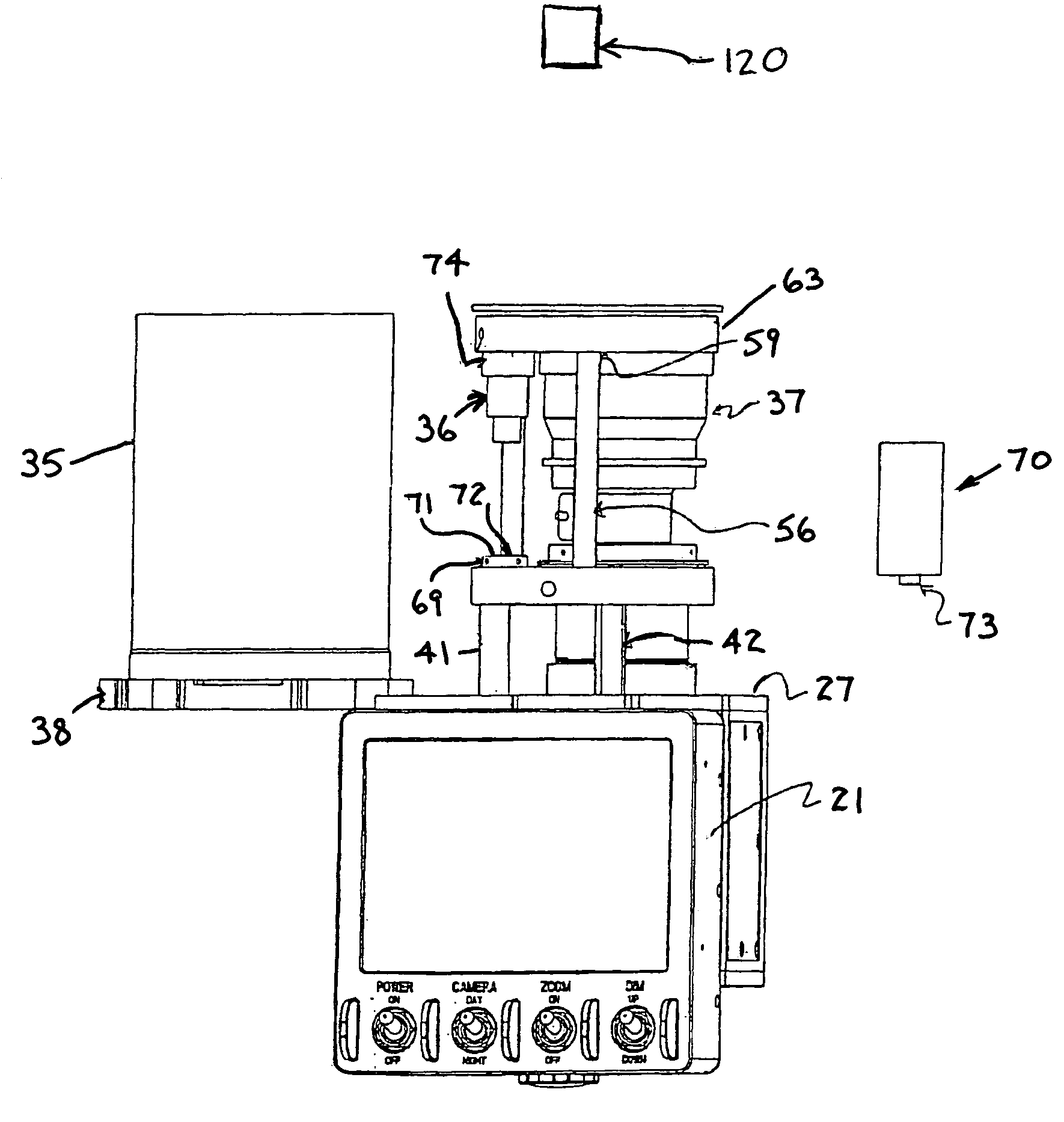
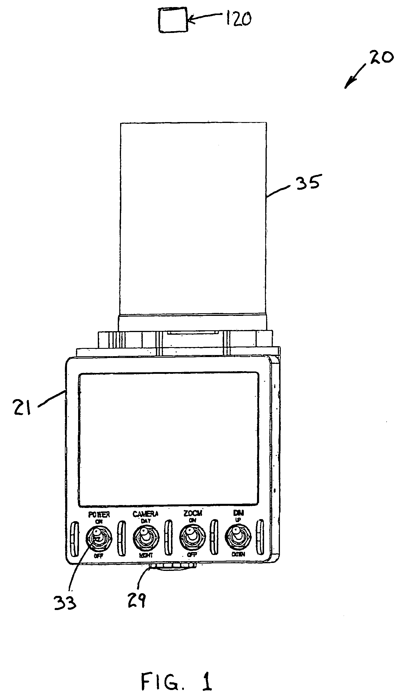
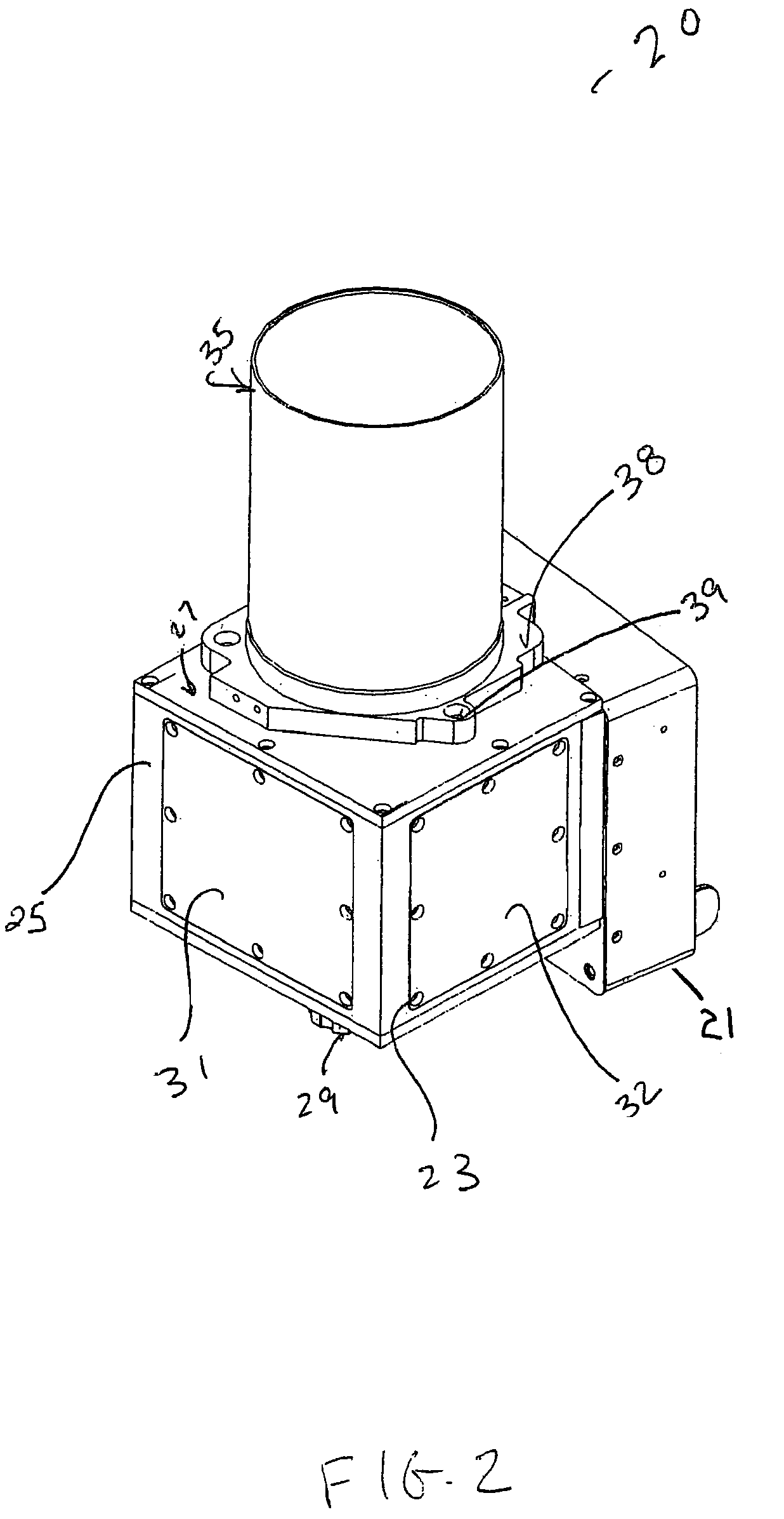
[0043]Referring to FIG. 1 is housing 20 for the electronics that is required for the processing of the detected images and providing a visible display of the image elements on a monitor 21, any suitable monitor known in the art but not limited to a Cathode Ray Tube, Liquid Crystal Display, etc. In the present embodiment a high resolution color flat panel display was implemented. The shape of the housing 20 is constructed so as to house the electronics require...


PUM


Abstract

The present invention includes a periscope, which has two camera objectives. The cameras are housed on top of the viewing monitor inside of a housing cell, so as to efficiently utilize the cabin space of the vehicle. One camera objective is a day camera bullet that may be used during day time or low light viewing. Another camera objective is the night board camera that may be used for night time viewing. Both cameras are electronically connected to a flat panel display, so that the optical picture may be displayed by others. In addition, the periscope of the present invention utilizes a heater sensor system that allows the day or night camera to be operated at or below temperatures of 32° Fahrenheit. The periscope of the present invention also implements an 18 mm image intensifier tube, which has the capability of detecting and amplifying low light level images during night time viewing and surveillance, under moonlight or starlight.

Description

FIELD OF INVENTION[0001]The present invention relates to an improved optical image forming apparatus and more particularly to a periscope system that allows for day and night imagery which includes a low light day system, coupled with a high resolution flat panel display.BACKGROUND OF THE INVENTION[0002]Periscopes are optical instruments for conducting observations from a concealed or protected position. A simple periscope consists essentially of reflecting mirrors or prisms at opposite ends of a tube with the reflecting surfaces parallel to each other, and at a 45° angle to the axis of the tube. The so-called field or tank periscope has been commonly used in trenches, behind parapets and earthworks, and in tanks to provide protected vision for the user. Periscopes are also used as viewing devices in military aircraft, in nuclear physics laboratories to observe radioactive reactions, and in particle accelerators.[0003]The physics behind periscope operation, as mentioned above, is ba...

Claims


Application Information

Patent Timeline
Patent Type & Authority Patents(United States)
IPC IPC(8): G02B23/12
CPCG02B23/08G02B23/12
Inventor TARTAGLIA, ROBERT
Owner SEILER INSTR & MFG
Why Eureka
Try Eureka