Detector for chromatograph and method for adjusting the same

a technology of chromatograph and chromatograph, which is applied in chemical methods analysis, instruments, material analysis, etc., can solve the problems of increasing the amount of data generated per unit time, increasing the required amount of memory, increasing the load on the communication system and the central processing unit (cpu), and reducing temporal resolution, so as to increase the absolute precision of the retention time of each peak, the effect of eliminating the unnatural display of the output screen showing the chromatogram and high degree of synchronization

Active Publication Date: 2010-05-13
SHIMADZU CORP
View PDF2 Cites 6 Cited by
  • Summary
  • Abstract
  • Description
  • Claims
  • Application Information

AI Technical Summary

Benefits of technology

[0025]In this adjustment method, only the simple operation of connecting the jig to the detector and pushing a button for ordering the start of adjustment, for example, is required to automatically set appropriate time adjustment parameters. Hence, an adjustment to eliminate the difference between the apparatus internal time and real time can be easily performed for each detector.
[0026]The detector for a chromatograph according to the present invention provides a high degree of synchronization of the apparatus internal time and real time, even in the case where the frequency deviation of a crystal oscillator for generating a reference clock signal is large. This increases the absolute precision of the retention time of each peak appearing on a chromatogram. Further, also in the case where an eluate from a column is bifurcated to be simultaneously and in parallel detected by a plurality of detectors, the progresses of the chromatograms created in real time based on the detection signals by the plurality of detectors can be synchronized, and the retention times for the same component can also be synchronized. In addition, the timing of the renewal of other monitoring information directly obtained from a column oven, for example, and the progress of a chromatogram can be synchronized. Therefore, the unnaturalness of the display on the output screen showing the chromatogram can be eliminated, increasing the user's sense of trust in the apparatus.

Problems solved by technology

The sampling period in the A / D converter is usually determined in view of the following factors: a short sampling period in the A / D converter increases the temporal resolution; however, it also increases the amount of data generated per unit time, increasing the required amount of memory as well as the load on the communication system and the central processing unit (CPU).
On the other hand, a long sampling period decreases the temporal resolution and steep peaks cannot be reproducibly detected, although it decreases the load on the communication system and CPU.
Since this output screen obviously shows that the apparatus internal time is not accurate, even if this does not cause substantial problems, the analysis operator doubts the accuracy of the detector, which might damage his or her credibility of it.
In particular, the longer the elapsed time becomes from the initiation of an analysis, the more the difference becomes between real time and the apparatus internal time, and the aforementioned problem becomes more prominent.
Nevertheless, there is also a more practical problem in that such an inaccuracy of the apparatus internal time as described earlier makes it difficult to reduce the error of the retention time.

Method used


Image

  • Detector for chromatograph and method for adjusting the same
  • Detector for chromatograph and method for adjusting the same
  • Detector for chromatograph and method for adjusting the same

Examples


Embodiment Construction

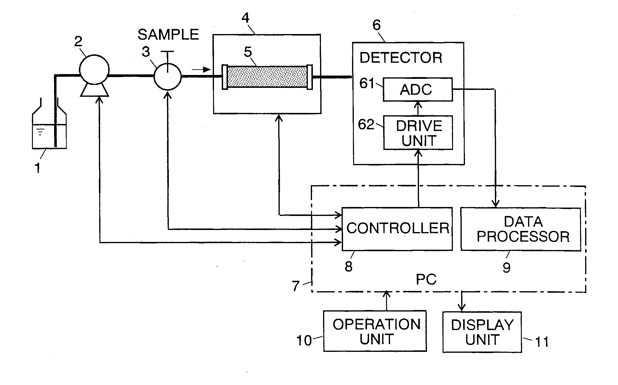
[0056]An embodiment of the liquid chromatograph (LC) system using the detector for a chromatograph according to the present invention will be described with reference to the attached figures. FIG. 1 is an entire schematic configuration diagram of the LC system according to the present embodiment.

[0057]In FIG. 1, the sending pump 2 sucks a mobile phase from the mobile phase container to send it to the column 5 through the injector 3 at an approximately constant flow rate. The injector 3 injects a sample liquid to the mobile phase at a predetermined time point, in correspondence to the control signal supplied from the controller 8. The sample liquid is sent to the column 5 by the flow of the mobile phase, and a variety of components in the liquid sample are temporally separated while passing through the column 5. The column 5 is contained in the column oven 4, and its temperature is controlled at a constant temperature or in accordance with a predetermined heating program under the co...


PUM

PropertyMeasurementUnit
frequencyaaaaaaaaaa
timeaaaaaaaaaa
timeaaaaaaaaaa

Abstract

The present invention provides a detector for a chromatograph capable of obtaining the accurate retention time, even if there is a frequency deviation of the clock signal for determining the timing of data sampling, by conforming the progress of the detector internal time accompanied with the repetition of the sampling to that of real time. In the detector, consecutive data sampling intervals are defined to be a time adjustment period, and in one time adjustment period, each of the sampling intervals whose number is given as the interpolation value M is elongated by a predetermined number of clock counts compared to each of the other sampling intervals. If the clock signal has a positive frequency deviation, the apparatus internal time determined by the clock signal progresses faster than real time. However, providing the interpolation value M corresponding to the amount of the frequency deviation elongates the time adjustment period on the basis of the apparatus internal time, to be conformed to the time adjustment period on the basis of real time which is determined by the sampling period.

Description

[0001]The present invention relates to a detector for a chromatograph such as a liquid chromatograph (LC) and gas chromatograph (GC). More precisely, it relates to a detector for a chromatograph incorporating an A / D converter for sampling an analog detection signal at predetermined data sampling intervals to convert it to digital values. It also relates to a method for adjusting such a detector.BACKGROUND OF THE INVENTION[0002]In a liquid chromatograph (LC), a variety of detectors, such as an absorbance detector, fluorescence detector, deferential refractive index detector, and electric conductivity detector, are used. Such detectors have an analog-to-digital (A / D) converter for sampling an analog detection signal at predetermined data sampling intervals and converting the sampled analog values into digital values, and send the digitized detection signal to a personal computer or other devices to perform a data processing task (refer to Patent Document 1 and other documents). The sa...

Claims


Application Information

Patent Timeline
Patent Type & Authority Applications(United States)
IPC IPC(8): G01D18/00G01N30/02
CPCG01N30/62G01N2030/626
Inventor BUNGO, HAJIME
Owner SHIMADZU CORP
Why Eureka
Try Eureka