Thermoelectric conversion element, thermoelectric conversion module, method for producing thermoelectric conversion element

Active Publication Date: 2010-05-13
MURATA MFG CO LTD
View PDF7 Cites 32 Cited by
  • Summary
  • Abstract
  • Description
  • Claims
  • Application Information

AI Technical Summary

Benefits of technology

[0039]In the thermoelectric conversion element according to various preferred embodiments of the present invention, each of the p-type thermoelectric conversion material, the n-type thermoelectric conversion material, and the insulating material is preferably an oxide material, and a connection electrode is not used. Thus, the element can be used at high temperatures without deterioration caused by oxidation.
[0040]When co-sintering the p-type oxide thermoelectric conversion material, the n-type oxide thermoelectric conversion material, and the insulating material, gaps between the materials are eliminated, thus, significantly increasing the bonding strength. Furthermore, co-sintering eliminates the need for a step of bonding the materials. Moreover, a connection electrode and a step of formin

Problems solved by technology

However, in the thermoelectric conversion element 50, the electrodes 56 and 58 are used to connect the two thermoelectric conversion materials 51 and 52, thereby disadvantageously producing contact resistance between the electrodes and the thermoelectric conversion materials.
Thus, the extent to which the occupancy of the thermoelectric conversion materials can be increased is limited.
Furthermore, since the insulation gap is provided between the two thermoelectric conversion materials 51 and 52, the element is susceptible to damage due to impact by, for example, dropping.
Thus, the element disadvantageously has low reliabili

Method used


Image

  • Thermoelectric conversion element, thermoelectric conversion module, method for producing thermoelectric conversion element
  • Thermoelectric conversion element, thermoelectric conversion module, method for producing thermoelectric conversion element
  • Thermoelectric conversion element, thermoelectric conversion module, method for producing thermoelectric conversion element

Examples


first preferred embodiment

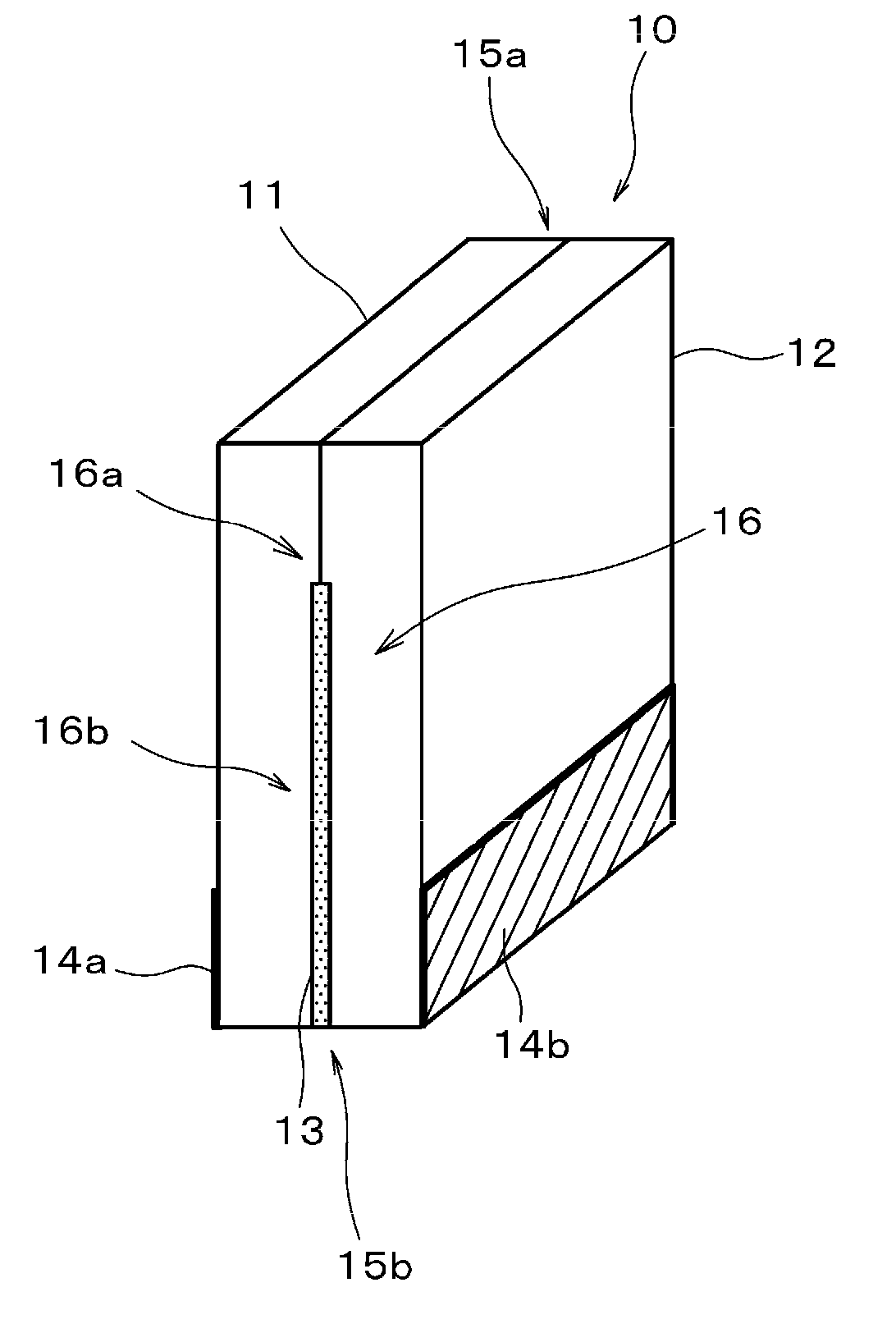
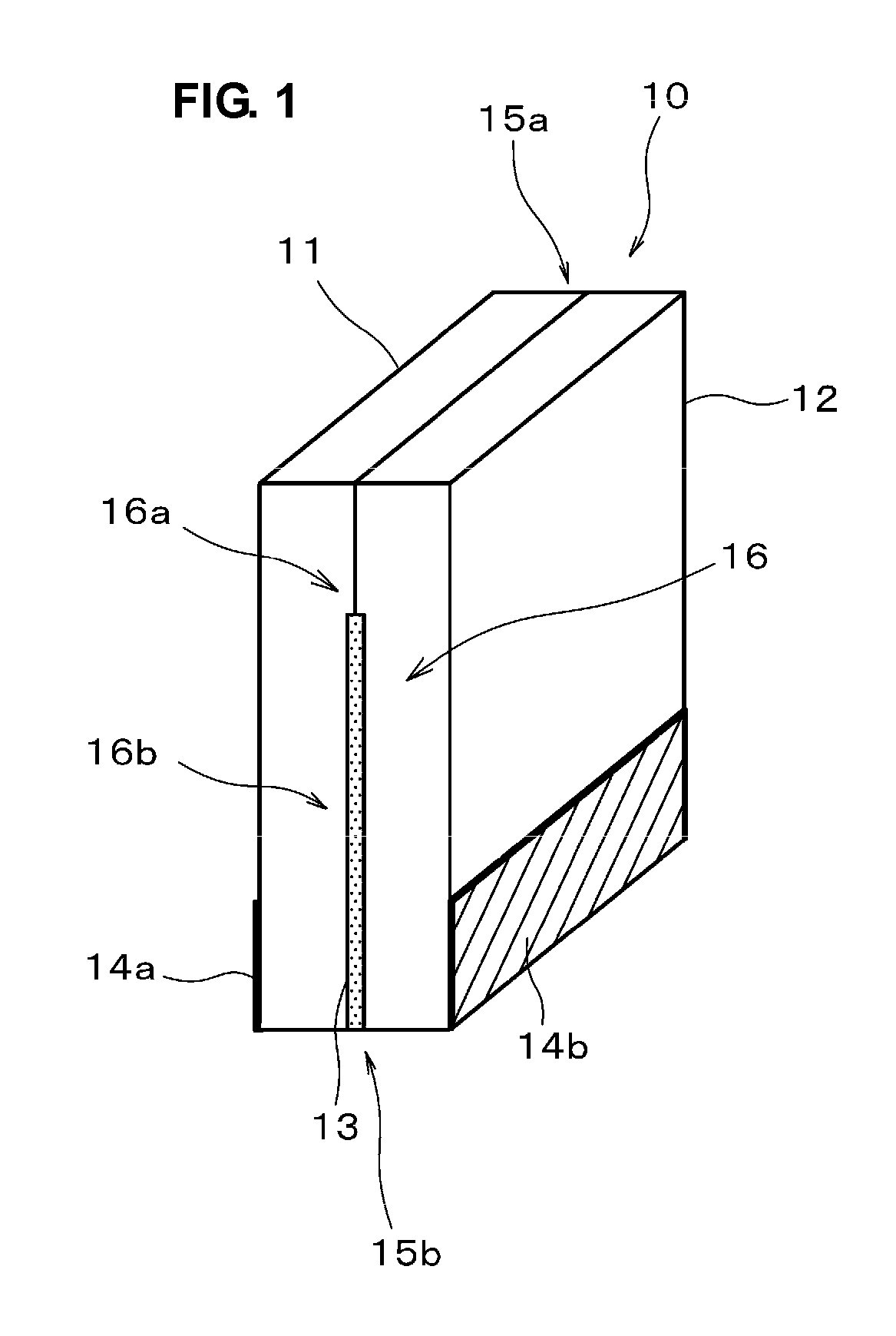
[0051]FIG. 1 shows a thermoelectric conversion element 10 according to a first preferred embodiment of the present invention. As shown in FIG. 1, the thermoelectric conversion element 10 according to the first preferred embodiment includes a p-type thermoelectric conversion material 11 (hereinafter, referred to as a “p-type oxide thermoelectric conversion material”) preferably primarily made of an oxide, for example, and an n-type thermoelectric conversion material 12 (hereinafter, referred to as an “n-type oxide thermoelectric conversion material”) preferably primarily composed of an oxide, for example.

[0052]In the thermoelectric conversion element 10 according to the first preferred embodiment, the p-type oxide thermoelectric conversion material 11 is directly bonded to the n-type oxide thermoelectric conversion material 12 without an electrode or other element provided therebetween in one region 16a of the junction surface 16 between the p-type oxide thermoelectric conversion mat...

second preferred embodiment

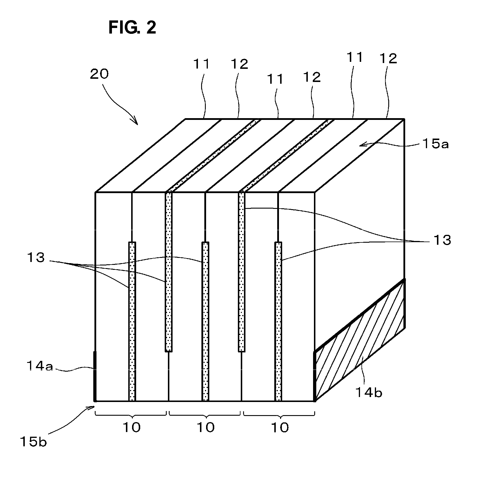
[0083]FIG. 2 shows a schematic structure of a thermoelectric conversion module according to a second preferred embodiment of the present invention.

[0084]A thermoelectric conversion module 20 according to the second preferred embodiment includes a plurality of bonded thermoelectric conversion elements 10 each having one p-type oxide thermoelectric conversion material 11 and one n-type oxide thermoelectric conversion material 12 and first and second electrodes 14a and 14b arranged at lower portions (lower-temperature-side junctions) 15b of both ends thereof.

[0085]FIG. 2 shows a structure including three thermoelectric conversion elements 10 each having a pair of the p-type oxide thermoelectric conversion material 11 and the n-type oxide thermoelectric conversion material 12. However, the number of the thermoelectric conversion elements 10 defining the thermoelectric conversion module 20 is not particularly limited.

[0086]Each of the thermoelectric conversion elements 10 used in the the...

examples

[0090]Examples of preferred embodiments of the present invention will be described below.

[0091]Here, an insulating material to be interposed between a p-type thermoelectric conversion material and an n-type thermoelectric conversion material was first studied when producing a thermoelectric conversion module according to an example of a preferred embodiment of the present invention.

[0092]Specifically, glass A, glass B, glass C, glass D, glass E, and glass F, having different softening points, shown in Table 1 below were prepared. Thermoelectric conversion modules were produced using materials each including one of the glasses and an oxide (forsterite (Mg2SiO4) powder, for example) as insulating materials. The effect of the softening point of the glass and the optimum ratio of the glass powder to the forsterite powder were studied.

Effect of Softening Point of Glass

[0093]Thermoelectric conversion materials and insulating materials described below were prepared.

[0094](a) p-type thermoe...


PUM

PropertyMeasurementUnit
Softening pointaaaaaaaaaa
Temperatureaaaaaaaaaa

Abstract

A thermoelectric conversion element, a thermoelectric conversion module, and a method for producing a thermoelectric conversion element are provided, each of the element and the module having a low contact resistance between a p-type thermoelectric conversion material and an n-type thermoelectric conversion material and being capable of being used at high temperatures without deterioration due to oxidation. A p-type oxide thermoelectric conversion material is primarily made of a substance having a layered perovskite structure represented by the formula: A2BO4, wherein A includes at least La, and B represents at least one element including at least Cu. An n-type oxide thermoelectric conversion material is primarily made of a substance having a layered perovskite structure represented by the formula: D2EO4, wherein D includes at least one of Pr, Nd, Sm, and Gd, and E represents at least one element including at least Cu. The p-type oxide thermoelectric conversion material, the n-type oxide thermoelectric conversion material, and a composite insulating material are co-sintered. A glass having a softening point of about 550° C. to about 750° C. is used as a glass defining the composite insulating material.

Description

BACKGROUND OF THE INVENTION[0001]1. Field of the Invention[0002]The present invention relates to a thermoelectric conversion element, a thermoelectric conversion module, and a method for producing a thermoelectric conversion element.[0003]2. Description of the Related Art[0004]To prevent global warming, the reduction of carbon dioxide is a critical issue. Thermoelectric conversion elements capable of directly converting heat into electricity have recently been receiving attention as one effective technique of utilizing waste heat.[0005]For example, as shown in FIG. 6, a thermoelectric conversion element 50 including a p-type thermoelectric conversion material 51, an n-type thermoelectric conversion material 52, lower-temperature-side electrodes 56, and a higher-temperature-side electrode 58 is known as a conventional thermoelectric conversion element.[0006]In the thermoelectric conversion element 50, two types of thermoelectric conversion materials 51 and 52 are provided for energy ...

Claims


Application Information

Patent Timeline
IPC IPC(8): H01L35/12B29C65/02
CPCH01L35/22H01L35/32H10N10/855H10N10/17
Inventor HAYASHI, SACHIKONAKAMURA, TAKANORI
Owner MURATA MFG CO LTD
Why Eureka
Try Eureka