Secondary battery protection circuit

a protection circuit and secondary battery technology, applied in the direction of battery overcharge protection, safety/protection circuit, transportation and packaging, etc., can solve the problems of excessive heating, excessive heating or ignition, and the battery as a whole may break or irrecoverably damage, so as to reduce the power consumption

Inactive Publication Date: 2010-05-13
SHARP KK
View PDF10 Cites 25 Cited by
  • Summary
  • Abstract
  • Description
  • Claims
  • Application Information

AI Technical Summary

Benefits of technology

[0016]The present invention is devised to solve the problems discussed above, and it is an object of the invention to provide a secondary battery protection circuit that

Problems solved by technology

In such an assembled lithium-ion secondary battery, if the voltage across a cell becomes higher than the upper limit voltage or lower than the lower limit voltage, the battery as a whole may break or be irrecoverably damaged.
When a lithium-ion secondary battery is overcharged, however, there are risks of excessive heating from a decomposition reaction of th

Method used


Image

  • Secondary battery protection circuit
  • Secondary battery protection circuit
  • Secondary battery protection circuit

Examples


example 1

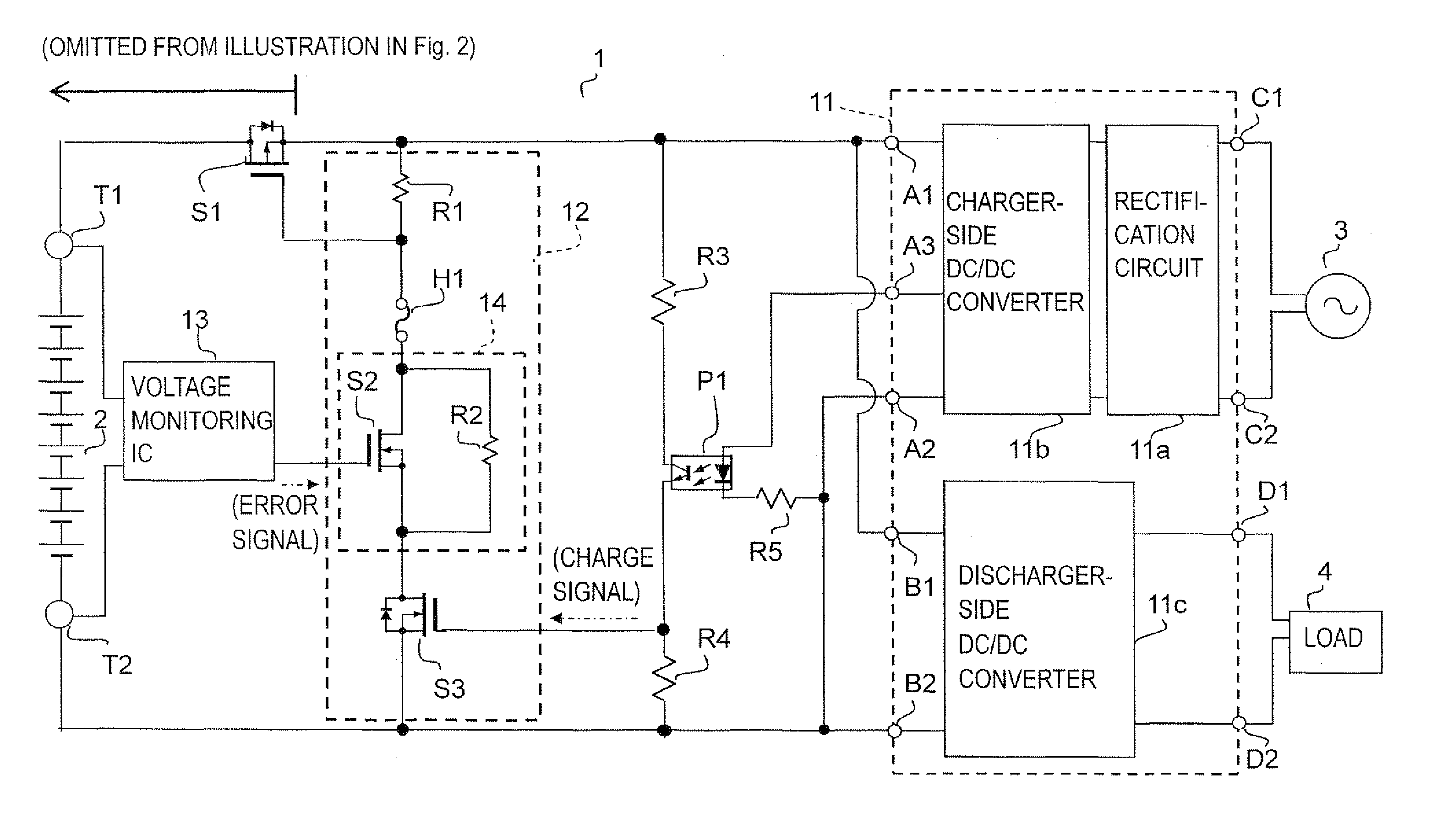
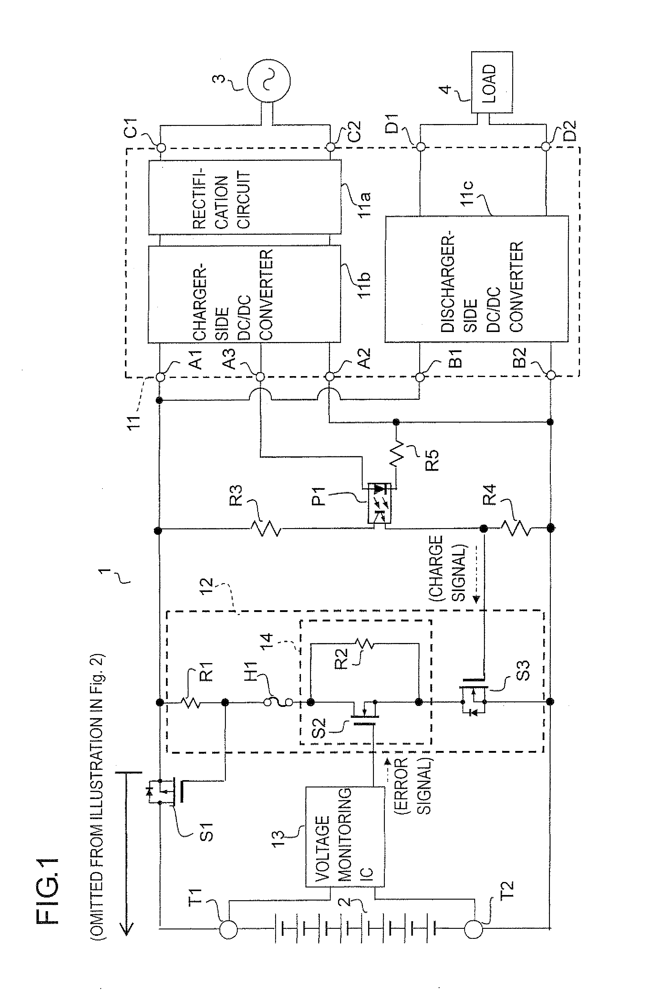
[0032]The configuration of a secondary battery protection circuit according to one embodiment (Example 1) of the invention is shown in FIG. 1. As shown in the figure, the secondary battery protection circuit 1 is provided with a charger / discharger 11, a first current path 12, a voltage monitoring IC 13, a switching device (MOSFET) S1, resistors R3 to R5, a photocoupler P1, a positive terminal T1, a negative terminal T2, and other components.

[0033]To the positive terminal T1, the positive electrode of a secondary battery 2 (a lithium-ion secondary battery) is connected, and to the negative terminal T2, the negative electrode of the secondary battery 2 is connected. Adopted as the secondary battery 2 here is one that yields 50 V when fully charged and about 40 V when sufficiently discharged.

[0034]The charger / discharger 11 is provided with a rectification circuit 11 a, a charger-side DC / DC converter 11b, and a discharger-side DC / DC converter 11c. The charger / discharger 11 is also provi...

example 2

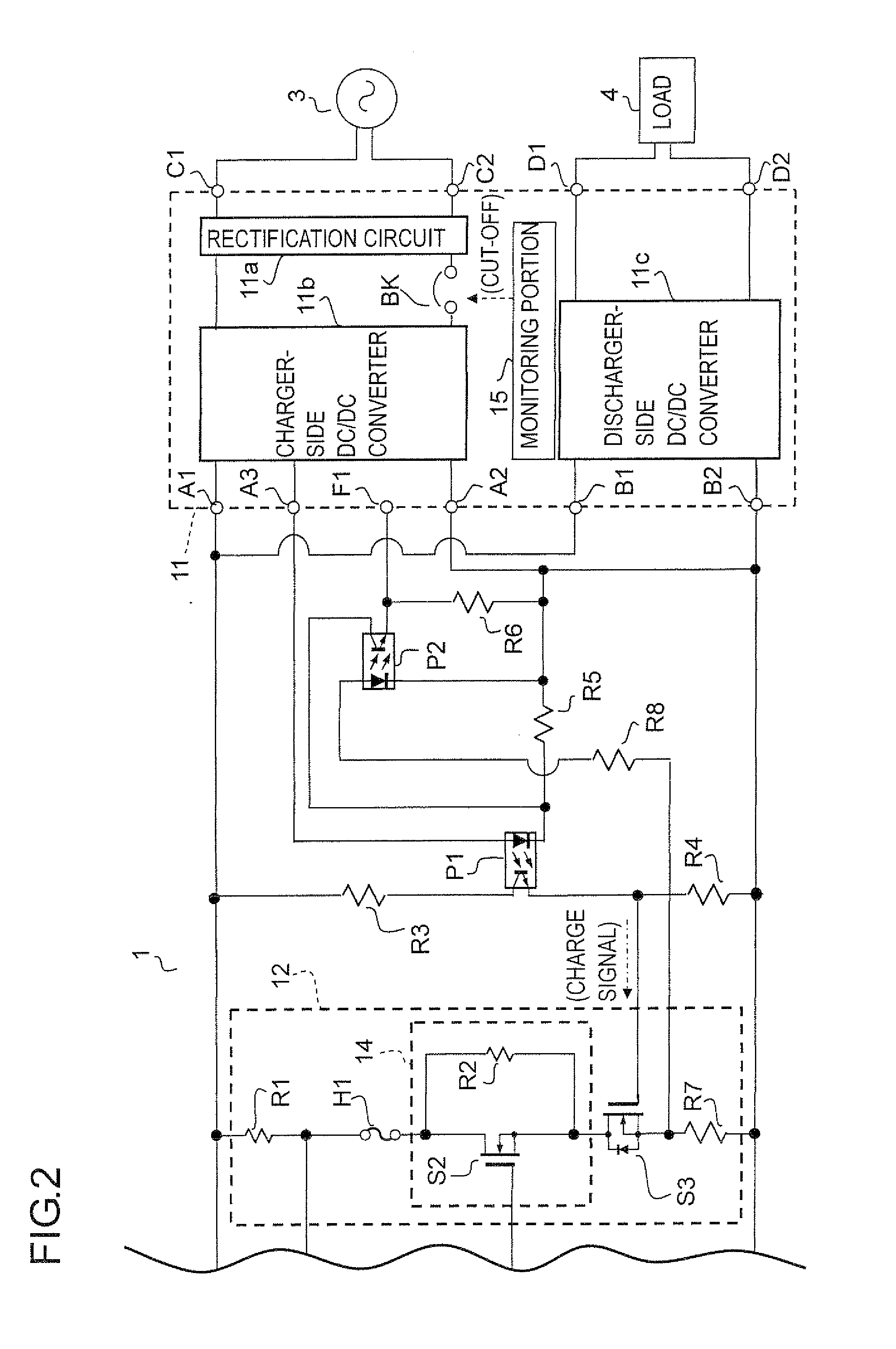
[0069]The configuration of a secondary battery protection circuit according to another embodiment (Example 2) of the invention is shown in FIG. 2. The configuration according to this example is basically similar to that according to Example 1. the difference being the additional provision of a monitoring portion 15, a breaker BK, a terminal F1 resistors R6 to R8, and a photocoupler P2 with a view to coping with an “ON failure” of the switching device S1 (for example, a state in which the switching device S1 fails in an ON state and does not return to an OFF state). Accordingly, not all the description of such parts as are common to Example 1 will be repeated. In FIG. 2, for want of space, (a left) part of the configuration is omitted from illustration; the configuration of the omitted part is the same as in FIG. 1.

[0070]The photocoupler P2 has a primary-side diode, which has an anode connected through the resistor R8 to between the source of the switching device S3 and one end of th...


PUM


Abstract

A secondary battery protection circuit has: a first switch that permits or inhibits charging of a secondary battery by switching a charge conductor between a conducting and a non-conducting state; a voltage detection portion that monitors the voltage of the secondary battery to output an error signal when the voltage is an overvoltage; and a first current path that has one end connected to the positive-side conductor and the other end connected to the negative-side conductor, and through which a current corresponding to the supplied electric power passes. The first current path, other than during charging of the secondary battery, is kept in a non-conducting state and, when the error signal is outputted while the first current path is in a conducting state, is irreversibly brought into a non-conducting state by a current of a predetermined amount or more passing therethrough. The first switch, when the first current path is in a conducting state, permits charging and, when the first current path is in a non-conducting state, inhibits charging. Thus, other than during charging, electric power consumption associated with overcharge protection is reduced, and once an overcharged state occurs, charging never again takes place.

Description

[0001]This nonprovisional application claims priority under 35 U.S.C. §119(a) on Patent Application No. 2009-014899 filed in Japan on. Jan. 27, 2009, the entire contents of which are hereby incorporated by reference.BACKGROUND OF THE INVENTION[0002]1. Field of the Invention[0003]The present invention relates to a secondary battery protection circuit that charges a secondary battery while protecting it from overcharging and the like.[0004]2. Description of Related Art[0005]Recent years have seen the spread of dispersed power source systems as an energy supply system with reduced CO2 emission. In a dispersed power source system, electric power produced by natural energy power generation, such as with solar batteries and by wind power, is converted to AC (alternating-current) power of a commercial frequency, which is then supplied to a commercial electric power network or to an AC load.[0006]A power supply or the like employing natural energy produces a varying output according to natu...

Claims


Application Information

Patent Timeline
IPC IPC(8): H02J7/04
CPCH02J7/0031H02J7/00302H02J7/00308
Inventor MATSUI, RYOJINISHIMURA, KAZUHITO
Owner SHARP KK
Why Eureka
Try Eureka