
Dc-to-dc converter comprising a reconfigurable capacitor unit

a capacitor unit and converter technology, applied in the direction of electric variable regulation, process and machine control, instruments, etc., can solve the problems of reducing the suitability of the present application and removing the benefit, so as to reduce the switching loss, minimize the output impedance, and minimize the effect of output impedan

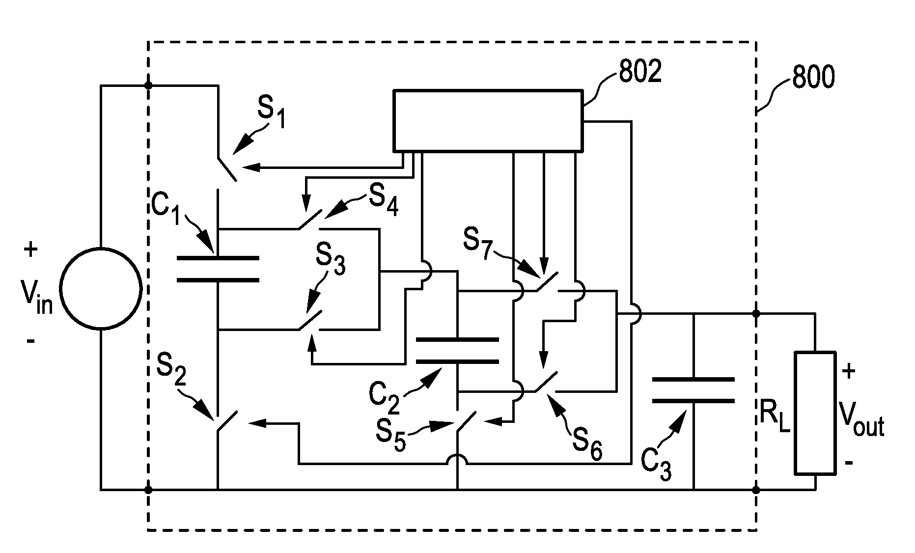
Active Publication Date: 2010-05-13
NXP BV
View PDF9 Cites 45 Cited by
  • Summary
  • Abstract
  • Description
  • Claims
  • Application Information

AI Technical Summary

Benefits of technology

[0016]A most suitable embodiment of a trench capacitor is a structure having a plurality of capacitor-electrode layers. This allows that more than one capacitive structure may be defined in a single trench. It will be understood that such an embodiment strongly reduces the losses due to interconnects. When in the following the term ‘trench multi-capacitor device of the invention’ is used, reference is made to such a structure. Applicant maintains its right to obtain separate patent protection for this structure.
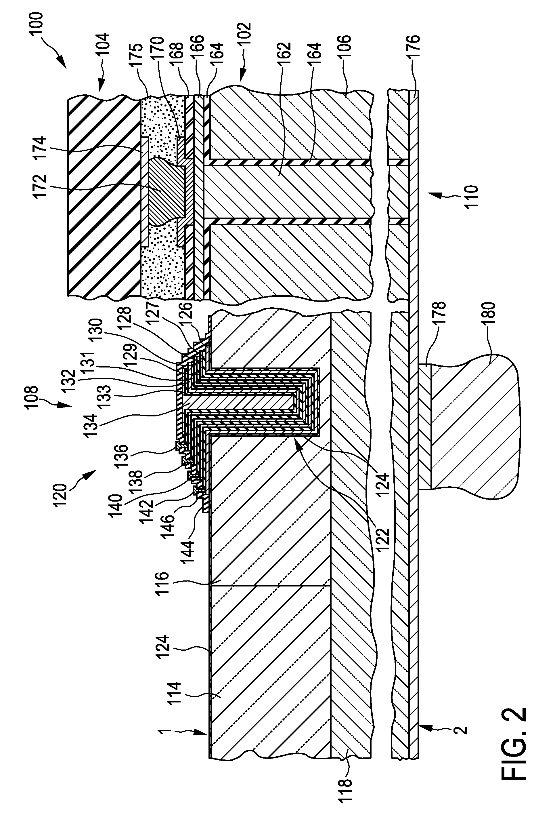
[0068]The trench multi-capacitor device can form a passive integration substrate of a system-in-package (SIP). It can integrate further passive components, such as inductors and resistors. In a further embodiment, the semiconductor substrate further comprises a through-substrate via extending from a first substrate side to an opposite second substrate side. The single-trench multi-capacitor and the through-substrate via are formed in respective trench openings via openings in the semiconductor substrate, which trench opening and via opening preferably have mutually equal lateral extensions. The trench multi-capacitor device of this embodiment forms a particularly cost-effective integration substrate for a system-in-package because the via opening and the trench opening in the semiconductor substrate can be fabricated simultaneously. This allows saving process steps otherwise required for separately fabricating the openings for through-substrate vias and for trench capacitors.

Problems solved by technology

The low-ohmic value is needed, as otherwise the interconnects would lead to losses that would take away the benefit of the reconfigurability.
Ferroelectric layers show hysteresis behaviour, for which reason they have a higher ESR and are less suitable for the present application.

Method used


Image

  • Dc-to-dc converter comprising a reconfigurable capacitor unit
  • Dc-to-dc converter comprising a reconfigurable capacitor unit
  • Dc-to-dc converter comprising a reconfigurable capacitor unit

Examples


Embodiment Construction

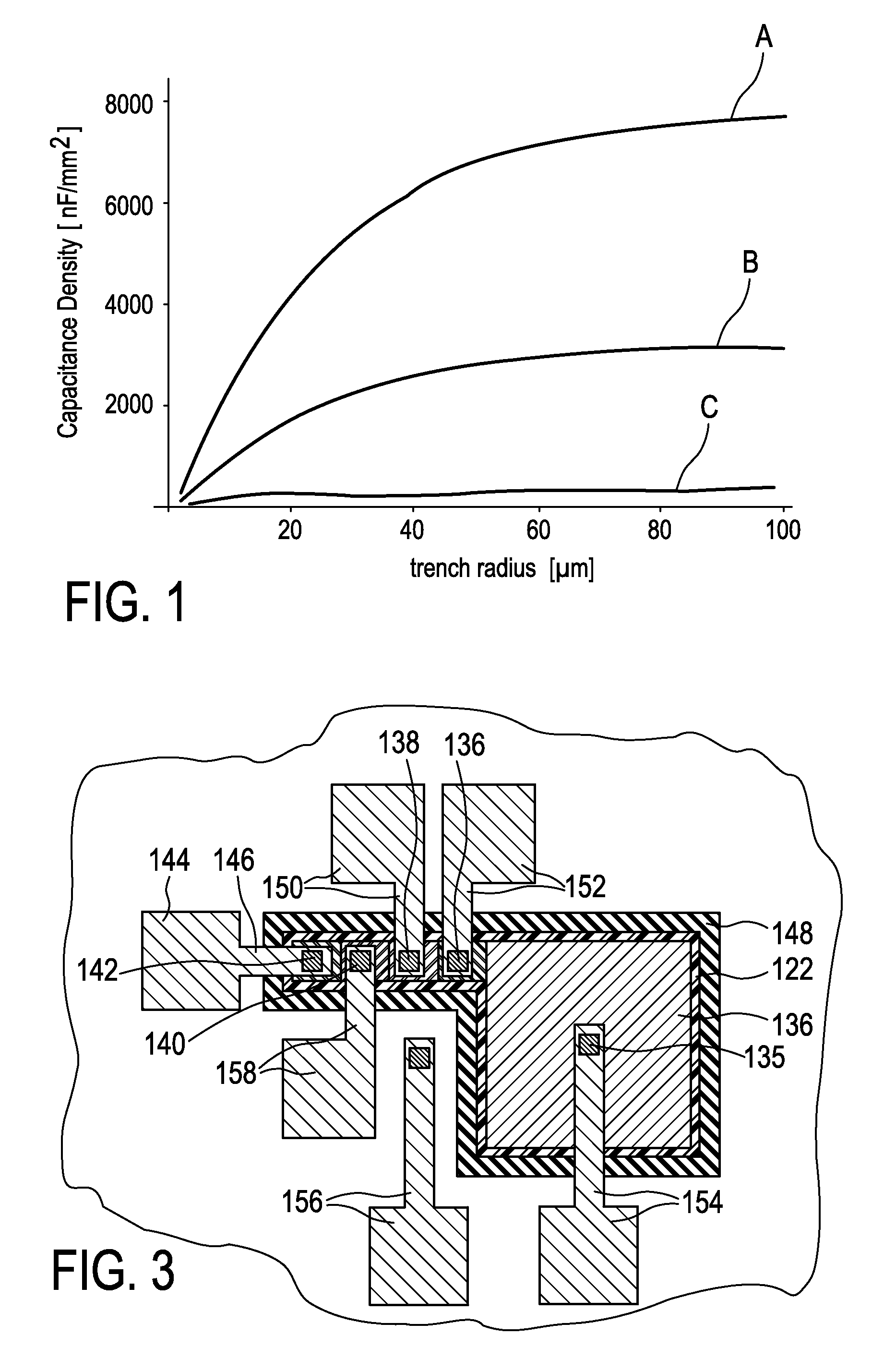
[0089]FIG. 1 is a diagram showing calculations of capacitance densities that can be achieved with a trench capacitor using multiple layer stacks. In the diagram the capacitance density in units of nF / mm2 (Nanofarad per square millimetre) is plotted as a function of a radius of a cylindrical trench, in which the trench capacitor is formed, in units of micrometer. The three curves A, B, and C shown were calculated for three different material combinations and processes that have values of a dielectric breakdown field, which values differ by a factor of 2. The breakdown field is considered as being proportional to the inverse of the square root of the relative dielectric constant of the dielectric material used for the dielectric layers of the trench capacitor. A constant breakdown voltage of the capacitor of 30 V was used as a constraint for all three material combinations and processes. An additional constraint was used for determining the respective metal thickness for a respective ...


PUM


Abstract

The present invention relates to a configurable trench multi-capacitor device comprising a trench in a semiconductor substrate. The trench has a lateral extension exceeding 10 micrometer and a trench filling includes a number of at least four electrically conductive capacitor-electrode layers. A switching unit is provided that comprises a plurality of switching elements electrically interconnected between different capacitor-electrode layers of the trench filling. A control unit is connected with the switching unit and configured to generate and provide to the switching unit respective control signals for forming a respective one of a plurality of multi-capacitor configurations using the capacitor-electrode layers of the trench filling.

Description

FIELD OF THE INVENTION[0001]The present invention relates to a DCDC converter[0002]The disclosure of EP05110488.3, PCT / IB / 2006 / 054063 (PH001923EP1), and of EP06113955.6 (PH005924EP1) is enclosed by reference in its entirety in the present application.BACKGROUND OF THE INVENTION[0003]It is well known that the a voltage ratio between an input voltage and an output voltage in a (capacitive) DC-to-DC converter is dependent on the capacitance of the converter.[0004]It is further well known that the capacitance of a capacitor device scales with the area of the capacitor electrodes, with the dielectric constant of the dielectric material between the capacitor electrodes, and with the inverse of the distance between the capacitor electrodes.[0005]To increase the area of the capacitor electrodes comprised in electronic devices, which are formed by integrated circuits on a semiconductor chip, trench capacitors have widely been used. In a trench capacitor, the electrodes are formed by electric...

Claims


Application Information

Patent Timeline
IPC IPC(8): H02M3/07
CPCH02M3/07H01L27/0805
Inventor KLOOTWIJK, JOHAN H.BERGVELD, HENDRIK J.ROOZEBOOM, FREDDYREEFMAN, DERKRUIGROK, JAAP
Owner NXP BV
Learn More