Eureka AIR delivers breakthrough ideas for toughest innovation challenges, trusted by R&D personnel around the world.

Light emitting diode having indium nitride

a technology of indium nitride and light-emitting diodes, which is applied in the direction of basic electric elements, electrical apparatus, semiconductor devices, etc., can solve the problems of increasing forward voltage, internal quantum efficiency deterioration, and high quantum indium amount further deteriorating internal quantum efficiency

Inactive Publication Date: 2010-05-20
SEOUL OPTO DEVICE CO LTD
View PDF7 Cites 21 Cited by
  • Summary
  • Abstract
  • Description
  • Claims
  • Application Information

AI Technical Summary

Benefits of technology

"The present invention provides a light emitting diode with a relieved strain in an active region. This is achieved by using a super lattice layer with alternating layers of different materials. The strain is created by the difference in lattice constant between the layers, which results in a more relaxed structure in the active region. This leads to improved performance and reliability of the diode. The invention also includes different variations of the super lattice layer structure, such as a multilayer structure and an InN layer. These variations further enhance the performance of the diode."

Problems solved by technology

Such strain causes deterioration of internal quantum efficiency by inducing a piezoelectric field in the quantum well.
For example, for a green light emitting diode, a high indium amount in the quantum well further deteriorates internal quantum efficiency, which is affected by the piezoelectric field.
However, a relatively wide energy band-gap of the electron blocking layer obstructs introduction of the holes into the multi-quantum well structure, thereby increasing the forward voltage.
Dissociation of the InGaN layer may deteriorate the quality of the active region, thereby promoting non-radiative recombination.

Method used


Image

  • Light emitting diode having indium nitride
  • Light emitting diode having indium nitride

Examples


Embodiment Construction

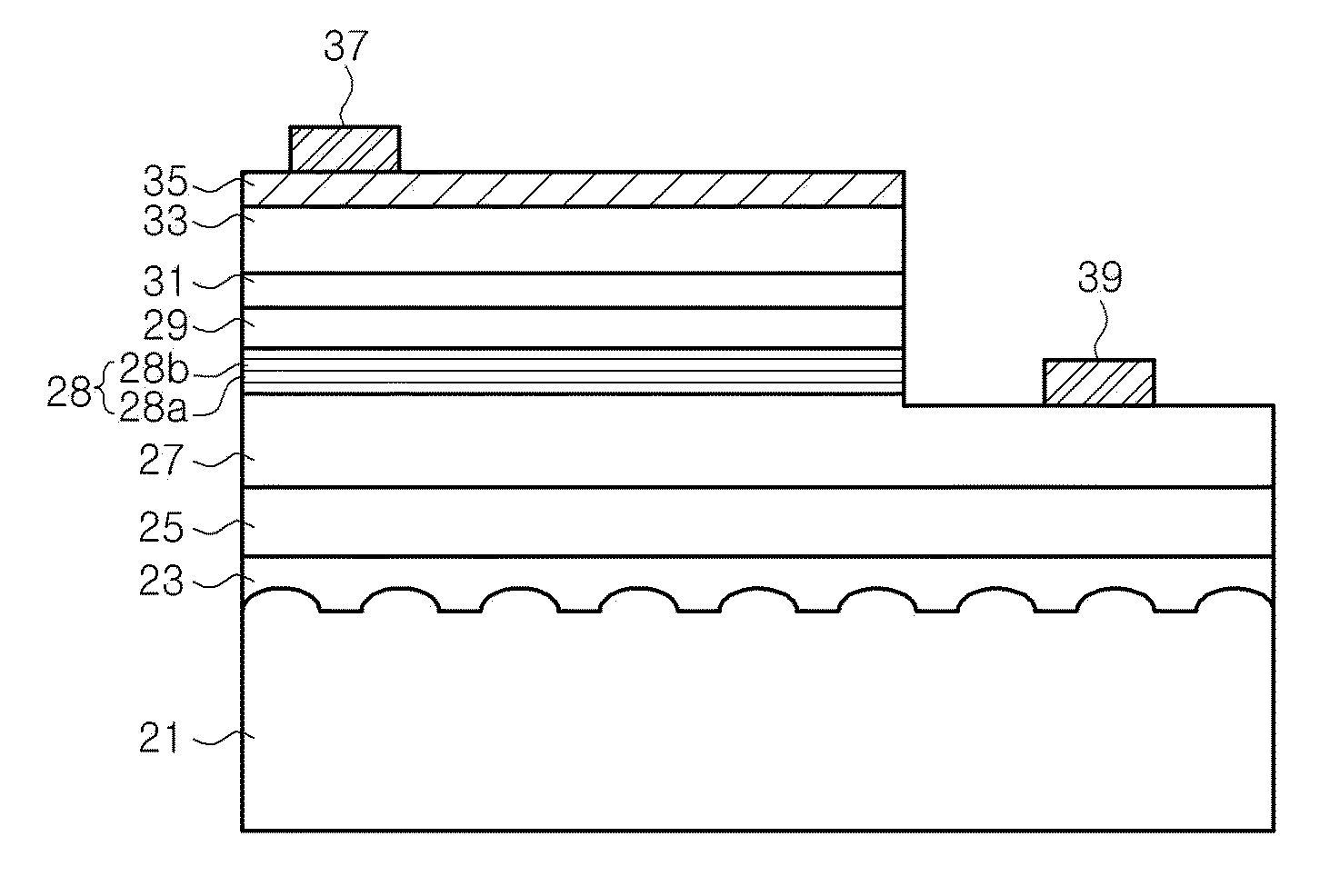
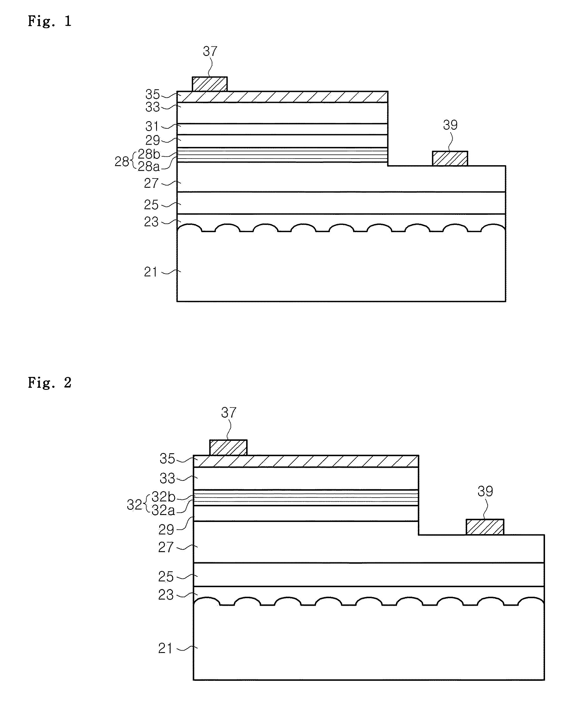
[0021]The invention is described more fully hereinafter with reference to the accompanying drawings, in which exemplary embodiments of the invention are shown. This invention may, however, be embodied in many different forms and should not be construed as limited to the exemplary embodiments set forth herein. Rather, these exemplary embodiments are provided so that this disclosure is thorough, and will fully convey the scope of the invention to those skilled in the art. In the drawings, the size and relative sizes of layers and regions may be exaggerated for clarity. Like reference numerals in the drawings denote like elements.

[0022]It will be understood that when an element or layer is referred to as being “on”, “connected to” or “coupled to” another element or layer, it can be directly on, connected or coupled to the other element or layer or intervening elements or layers may be present. In contrast, when an element is referred to as being “directly on,”“directly connected to” or...


PUM


Abstract

The present invention relates to a light emitting diode (LED) including an n-type nitride semiconductor layer, a p-type nitride semiconductor layer, and an active region interposed between the n-type nitride semiconductor layer and the p-type nitride semiconductor layer. The active region may include an InGaN quantum well layer. The LED may further include a super lattice layer interposed between the n-type nitride semiconductor layer and the active region. The super lattice layer may be a structure wherein InN layers and InxGa1-xN (0≦x<1) layers are alternately stacked. The active layer may be formed on the InGaN / InxGa1-xN super lattice layer, so that strain can be relieved in the active region and so that crystallinity of the quantum well can be improved to increase an electron-hole recombination rate.

Description

CROSS REFERENCE TO RELATED APPLICATIONS[0001]This application claims priority from and the benefit of Korean Patent Application No. 10-2008-0115475, filed on Nov. 20, 2008, and Korean Patent Application No. 10-2008-0135165, filed on Dec. 29, 2008, which are hereby incorporated by reference for all purposes as if fully set forth herein.BACKGROUND OF THE INVENTION[0002]1. Field of the Invention[0003]Exemplary embodiments of the present disclosure relate to a light emitting diode (LED) and, more particularly, to a light emitting diode including indium nitride.[0004]2. Discussion of the Background[0005]Generally, nitride-based semiconductors are widely used in ultraviolet (UV), and blue / green light emitting diodes or laser diodes for light sources of full-color displays, traffic lights, general lighting fixtures, and optical communication devices. A light emitting device having a nitride-based semiconductor may include an active layer of a multi-quantum well structure between a n-type n...

Claims


Application Information

Patent Timeline
Patent Type & Authority Applications(United States)
IPC IPC(8): H01L33/00
CPCH01L33/32H01L33/06
Inventor KIM, DAE WONKAL, DAE SUNGYE, KYUNG HEEYOO, HONG JAE
Owner SEOUL OPTO DEVICE CO LTD
Why Eureka
Eureka Blog
Learn More