[0010]The present invention is created in view of the above described problems, and it is an object of the present invention to provide an optical displacement gage having an expanded measurable range without lowering measurement accuracy. In particular, it is an object of the present invention to expand the measurable range of the optical displacement gage that decides a displacement amount from phase of frequency component corresponding to
spatial frequency at the local maximum. It is also an object of the present invention to provide an optical displacement gage with increased measurement accuracy by raising the wavelength resolution of the spectroscope.
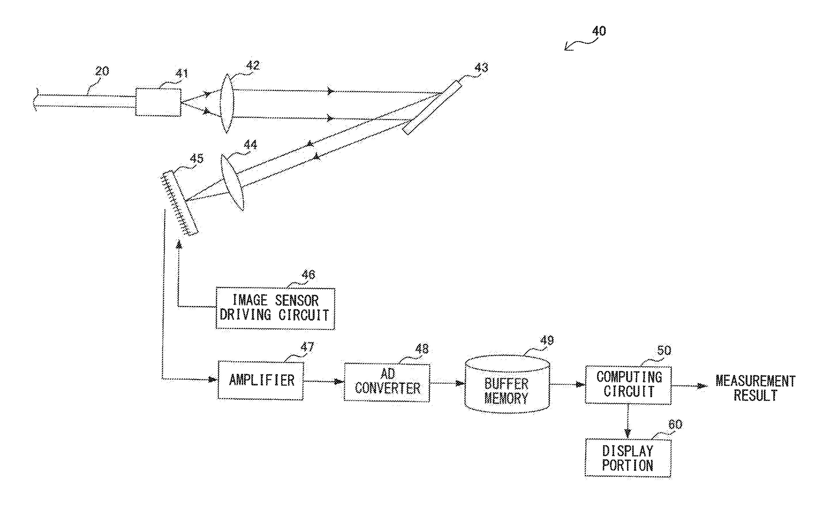
[0013]In this optical displacement gage, a displacement amount of the object to be measured is decided by utilizing interference between reflection light reflected from the
reference surface and reflection light from the object to be measured. In this case, the
optical intensity distribution with respect to the wave number of the interference light after the dispersion is converted into the
optical intensity distribution with respect to
spatial frequency of the
light intensity for the wave number, and local maximum therein is extracted. Then, a displacement amount is decided based on the phase of the frequency component corresponding to the
spatial frequency at the local maximum in the
optical intensity distribution with respect to the wave number. The phase of the frequency component is determined based on the relative phase decided within a range of 360 degrees and the past decision result of the relative phase, as absolute phase obtained by combining the relative phases. According to this structure, a displacement amount is decided based on the phase of the frequency component corresponding to the spatial frequency at the local maximum. Therefore, it is hardly affected by
dirt on the surface of the object to be measured, so that measurement accuracy can be improved compared with the type in which a displacement amount is decided directly from the spatial frequency at the local maximum. In addition, the relative phase is combined so as to determine the absolute phase, and a displacement amount is decided based on the absolute phase. Therefore, the measurable range can be expanded.
[0016]An optical displacement gage according to a fourth aspect of the present invention, in addition to the structure described above, includes a structure in which the
light intensity local maximum extracting unit performs a barycenter process of intensity data of the individual spatial frequency so as to determine the local maximum. According to this structure, the local maximum is determined by the barycenter process of the intensity data of the individual spatial frequency. Therefore, measurement accuracy of the displacement amount can be improved compared with the case where peak point in the intensity data is simply regarded as local maximum.
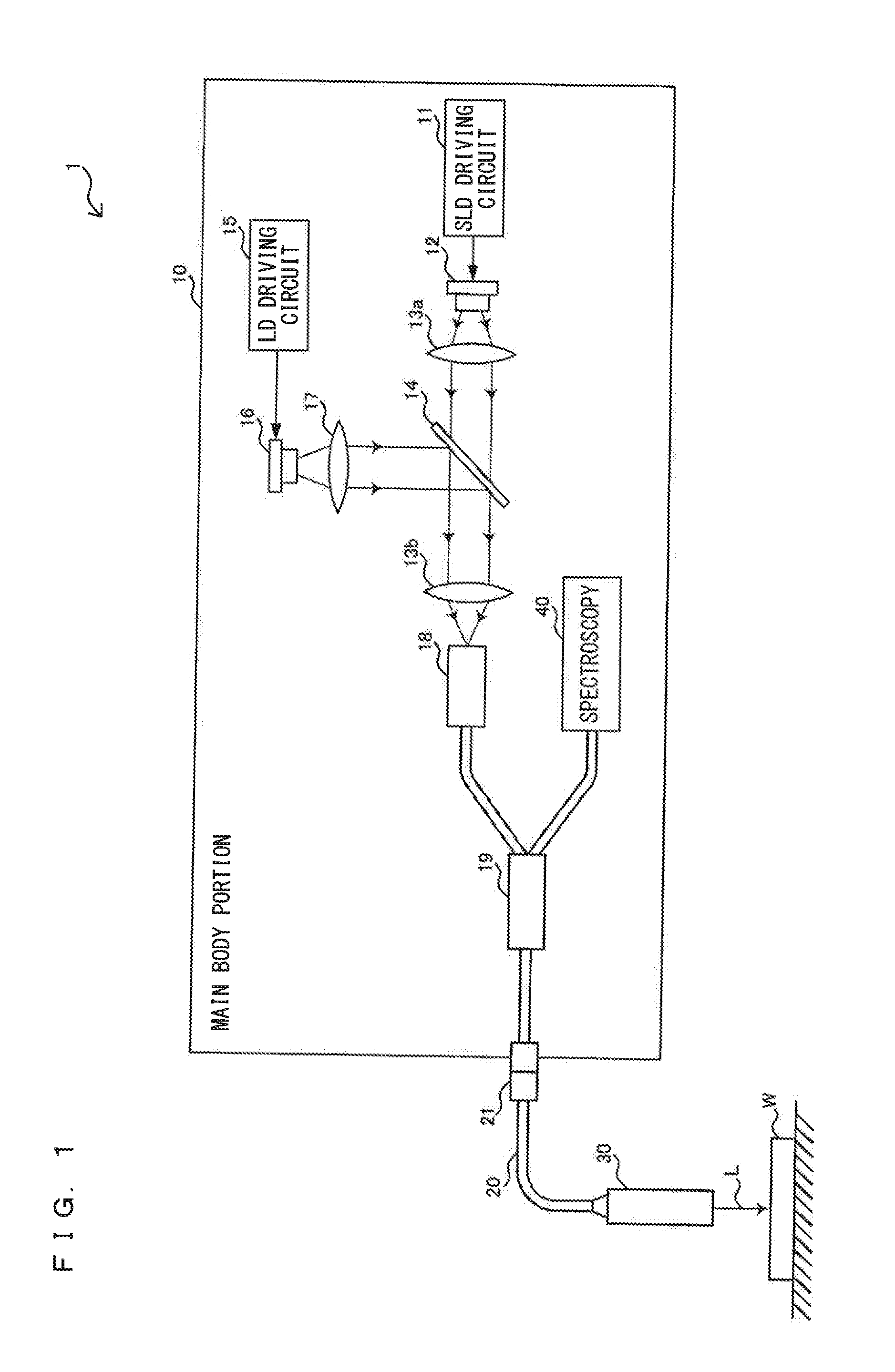
[0018]An optical displacement gage according to a sixth aspect of the present invention, in addition to the structure described above, has a structure in which a
single mode optical fiber that transmits light in a single mode is used for transmitting the sensing light and the interference light. According to this structure, occurrence of an
optical path difference in the light propagating in the
optical fiber can be suppressed. Therefore, measurement accuracy of the displacement amount can be further improved.
[0019]An optical displacement gage according to a seventh aspect of the present invention, in addition to the structure described above, has a structure in which the sensing light is
near infrared light having a narrow wavelength bandwidth compared with
white light. According to this structure, a light amount of each wavelength can be secured sufficiently so that the wavelength resolution of the spectroscope can be raised sufficiently. Therefore, measurement accuracy of the displacement amount can be further improved.
[0020]According to the optical displacement gage of the present invention, the displacement amount is decided based on the phase of the frequency component corresponding to the spatial frequency at the local maximum. Therefore,
dirt on the surface of the object to be measured hardly affects, so that the measurement accuracy can be improved compared with the case where the displacement amount is decided directly from the spatial frequency at the local maximum. In addition, the relative phase is combined so as to determine the absolute phase, and the displacement amount is decided based on the absolute phase. Therefore, the measurable range can be expanded. Thus, an optical displacement gage having the expanded measurable range without lowering the measurement accuracy can be realized. In addition, the sufficient light amount can be secured for each wavelength, so that the wavelength resolution of the spectroscope can be raised sufficiently. Therefore, the measurement accuracy of the displacement amount can be further improved.

